Solar LED (light emitting diode) pest-killing lamp adopting flyback-boost and working method thereof

A technology of LED insecticidal lamps and LED lamps, which is applied to the application, devices for catching or killing insects, semiconductor devices of light-emitting elements, etc., can solve the problems of reducing the effect of attracting insects, unfavorable promotion, and automatically turning off lights, etc., to achieve improved Stability and reliability, prolonging the life of LED lamps, and reducing the cost of use

Inactive Publication Date: 2012-07-11
连云港陆亿建材有限公司 +1
View PDF7 Cites 3 Cited by
  • Summary
  • Abstract
  • Description
  • Claims
  • Application Information

AI Technical Summary

Problems solved by technology

[0011] The market lacks a design that can use the characteristics of LED itself to use software control on the same light to realize the light wavelength adjustment design for the visual sensitivity curve characteristics of various pests, so that the same light can be used to kill different pests. The purpose, which to a certain extent caused the blind spot of killing, so that the insecticidal lamp did not realize the maximum benefit it could have produced
[0012] 2. Solar LED insecticidal lamps have not been fully utilized
At night, as the light becomes weaker, the control system will still automatically turn on the LED lights, and the life of the LED lights, batteries, and photovoltaic modules is limited, which makes insecticidal lights become so-called vases. , did not make full use of the resource of insecticidal lamps, resulting in increased investment costs for farmers and unnecessary loss of fixed assets
[0013] 3. The switch setting of the insecticidal light is not flexible enough
However, the solar LED insecticidal lamp currently on the market is designed according to the light. When the light is dark to the set value, it will automatically turn on the light, and when the light brightness reaches a certain set value, it will automatically turn off the light. There is no such protection against pests. Features for switch control design
During the period before and after the intensive activities of pests, the opening of the insecticidal lamps only acted as street lights to some extent, but did not have a good insecticidal effect, which to a certain extent caused resources waste, prolong the service time of batteries and LED lamps, shorten their service life, and increase the investment cost of farmers to a certain extent, increase the burden on farmers, and reduce the economic benefits of farmers
[0014] In addition, the tendency of phototactic pests to dynamic colors is much greater than that of relatively static conditions, and the current solar insecticidal lamps are always on when they are used at night. For insects, LED lights are a relatively static color. The light source, compared with the dynamic light source for their stimulation and attractiveness, is not very strong for a long time, which reduces the effect of attracting insects to a certain extent
[0015] 4. Inefficiency
Although solar energy is a renewable energy source, subject to technological development, the conversion efficiency of photovoltaic modules is still relatively low at this stage. In this way, the number of photovoltaic modules and the capacity of batteries need to be increased to meet specific load conditions such as LED lights and high-voltage power grids. , which directly leads to an increase in the cost of
At the same time, existing insecticidal lamps generally use DC 12V to be raised to AC 220V through an inverter, and the 220V AC is then boosted to a high voltage above 3000V for high-voltage power grids. This implementation method has large losses, low conversion efficiency, and high system implementation costs. , is not conducive to promoting

Method used


Image

  • Solar LED (light emitting diode) pest-killing lamp adopting flyback-boost and working method thereof
  • Solar LED (light emitting diode) pest-killing lamp adopting flyback-boost and working method thereof

Examples


Embodiment Construction

[0028] The present invention will be further described below in conjunction with specific examples.

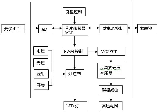
[0029] Such as figure 1 , a kind of solar LED insecticidal lamp adopting flyback step-up of the present invention, it comprises:

[0030] Including photovoltaic modules, batteries, LED lights and high-voltage power grids. In addition, the insecticidal lamp also includes AD conversion modules, intelligent control boards, single-chip controllers MCU, battery control modules, PWM controllers, MOSFETs ), a flyback step-up transformer and a rectifier filter module. The photovoltaic module is connected to the battery through the AD conversion module, the single-chip controller MCU, and the battery control module. The single-chip controller MCU is also connected to the PWM controller. It is connected to the high-voltage power grid through MOSFET, flyback step-up transformer, and rectification and filtering module, and the other is connected to LED lights.

[0031] The keyboard cont...


PUM


Abstract

The invention provides a solar LED (light emitting diode) pest-killing lamp adopting flyback-boost and a working method thereof. The lamp is characterized in that a photovoltaic module is connected with a storage battery by an AD (analog-digital) conversion module, an intelligent control panel and a storage battery control module in sequence; the intelligent control panel is connected with a PWM (pulse width modulation) controller; and the PWM controller is connected with a high-voltage power network by an MOSFET (metal-oxide-semiconductor field effect transistor), a flyback boosting transformer and a rectifying and filtering module on one path and is connected with an LED lamp on the other path. The working method comprises the following steps: current generated by the photovoltaic module passes through the intelligent control panel and the storage battery control module to charge the storage battery and then the storage battery supplies power to the LED lamp on one path via the intelligent control panel and the PWM controller in sequence and supplies power to the high-voltage power network on the other path via the MOSFET, the flyback boosting transformer and the rectifying and filtering module. The lamp and the working method have the following advantages: under the control of the PWM controller, the 12V direct current voltage output by the storage battery is directly converted to direct current voltage of above 3000V by the flyback boosting transformer, and the high voltage is used by the high-voltage power network after being filtered and rectified.

Description

[0001] technical field [0002] The invention relates to an insecticidal lamp, in particular to a solar LED insecticidal lamp adopting a flyback voltage boost. Background technique [0003] In the vast rural areas of our country, the main method of pest control is to use traditional pesticides to prevent and control agricultural pests. Although this control method can achieve a good insecticidal effect in a short period of time, agricultural pests will gradually become more effective after a certain period of adaptation. These drugs have developed resistance, making the original amount of pesticides not enough to kill the pests, and then farmers will increase the dosage of pesticides, and as the resistance of the pests increases, the amount of pesticides also increases linearly. [0004] In addition, due to the pesticide residues produced by a large number of pesticides and the accumulation of pesticides in the food chain formed by the residues, it will not only cause enviro...

Claims


Application Information

Patent Timeline
Patent Type & Authority Applications(China)
IPC IPC(8): A01M1/04A01M1/22H02N6/00H02J7/00H02J3/38F21S9/03F21Y101/02F21Y115/10
CPCY02E10/563Y02E10/56
Inventor 宋永江李万杰陆振刚
Owner 连云港陆亿建材有限公司
Why Eureka
Try Eureka