Solder strip of solar module

A technology for solar modules and ribbons, applied in electrical components, semiconductor devices, photovoltaic power generation, etc., can solve the problems of large difference in thermal expansion coefficient, uneven stress distribution, cell rupture, etc., to reduce internal stress and reduce fragmentation rate. Effect

Inactive Publication Date: 2012-07-11
TRINA SOLAR CO LTD +1
View PDF7 Cites 38 Cited by
  • Summary
  • Abstract
  • Description
  • Claims
  • Application Information

AI Technical Summary

Problems solved by technology

[0003] However, in actual use, due to the large difference in thermal expansion coefficient between the copper strip and the battery sheet, no matter in the cooling process after welding or due to changes in the ambient temperature, the two will generate a lot of stress at the edge o

Method used


Image

  • Solder strip of solar module
  • Solder strip of solar module
  • Solder strip of solar module

Examples


Embodiment Construction

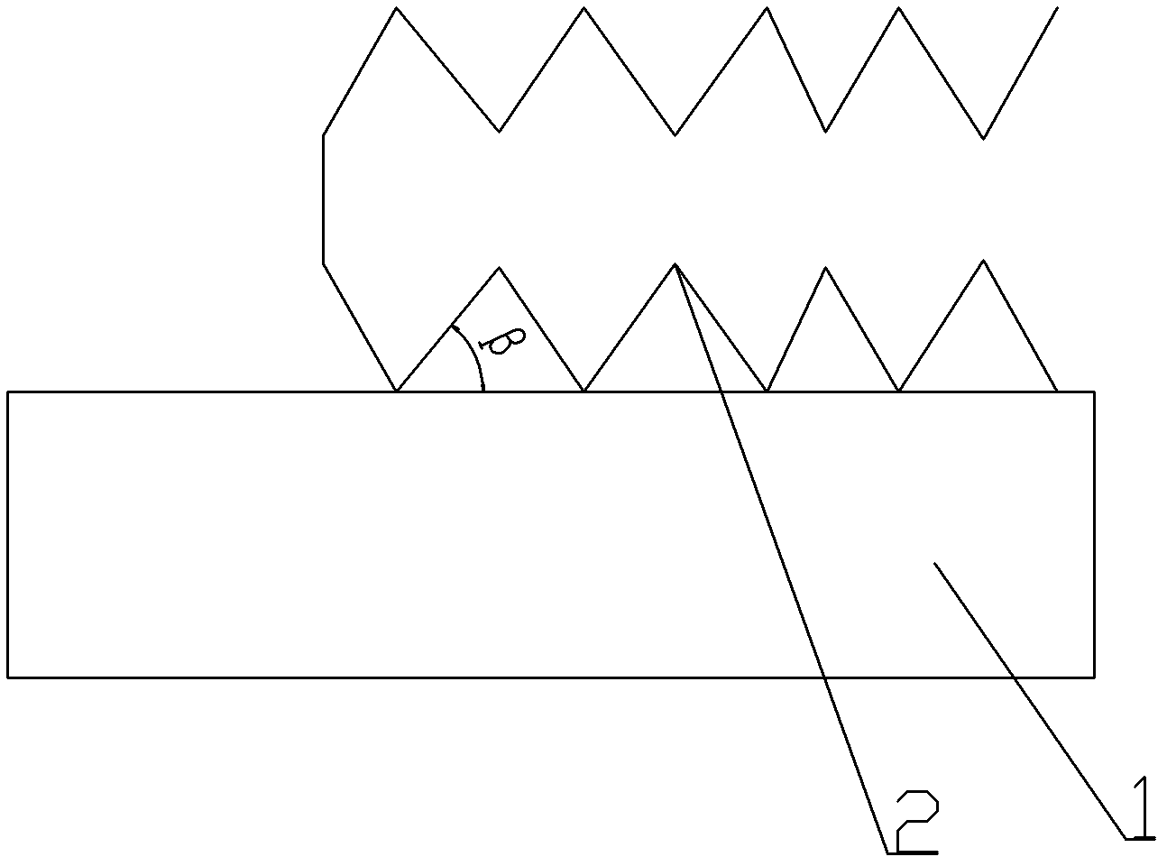
[0018] Such as figure 2 , 3 , 4, 5 and 6, a kind of solar module welding ribbon, V-shaped grooves 2 are made on the upper and lower surfaces of the welding ribbon, or only V-shaped grooves are made on the welding surface of the welding ribbon and the battery sheet, and the V-shaped groove 2 perpendicular to the length of the ribbon. The thickness of the welding strip is 0.15mm-0.5mm, the angle β of the V-shaped groove 2 is 20°-75°, and the vertical distance from the peak of the V-shaped groove 2 on the upper surface to the peak of the V-shaped groove 2 on the lower surface is 0.10mm ~1.00mm.

[0019] A preferred embodiment is: the angle β of the V-shaped groove 2 is 60°, and the vertical distance from the peak of the V-shaped groove 2 on the upper surface to the peak of the V-shaped groove 2 on the lower surface is 0.5mm.


PUM

PropertyMeasurementUnit
Thicknessaaaaaaaaaa

Abstract

The invention relates to a solder strip of a solar module. V-shaped groove are formed on upper and lower surfaces of the solder strip, or a V-shaped groove is only formed on the soldered surface of the solder strip and a cell sheet; and the V-shaped groove is vertical to the length direction of the solder strip. The solder strip is 0.15-0.5 mm in thickness; the angle beta of the V-shaped groove is 20-75 degrees; and the vertical distance from the peak of the V-shaped groove on the upper surface to the peak of the V-shaped groove on the lower surface is 0.10-1.0 mm. The solder strip of the solar module has the following advantages that: through bending the solder strip, the internal stress of the solar cell sheet after being welded is largely reduced in the process of expanding with heat and contracting with cold so that the breaking rate of the solar cell and the hidden crack possibility of the solar module are reduced.

Description

technical field [0001] The present invention relates to solar module soldering ribbons. Background technique [0002] At present, solar modules are connected to solar cells by ribbons. Due to the good welding performance and electrical conductivity of the ribbons, each solar cell forms a complete electrical path after welding, so that the solar modules are produced under the irradiation of sunlight. Current and voltage can be transmitted in the ribbon, which provides a reliable basis for utilizing solar energy. Such as figure 1 , The common solder strip structure includes three parts, the middle is copper strip, and the upper and lower layers are tin alloy layer or silver layer, and its thickness only accounts for less than 25% of the total thickness. [0003] However, in actual use, due to the large difference in thermal expansion coefficient between the copper strip and the battery sheet, no matter in the cooling process after welding or due to changes in the ambient tem...

Claims


Application Information

Patent Timeline
IPC IPC(8): H01L31/05
CPCY02E10/50
Inventor 焦海军
Owner TRINA SOLAR CO LTD
Why Eureka
Try Eureka