Piezoelectric-static compound micro machine vibration energy collector and manufacture method thereof

A vibration energy harvesting, composite technology, applied in generators/motors, piezoelectric effect/electrostrictive or magnetostrictive motors, manufacturing microstructure devices, etc., can solve problems such as poor stability and performance, and achieve Avoid device instability and poor performance, improve collection efficiency, and achieve broadband collection effects

Inactive Publication Date: 2012-07-11
XIAMEN UNIV +1
View PDF3 Cites 26 Cited by
  • Summary
  • Abstract
  • Description
  • Claims
  • Application Information

AI Technical Summary

Problems solved by technology

[0005] The purpose of the present invention is to provide a piezoelectric device with a relatively simple preparation process, which can overcome the disadvantages of poor device stability and performance caused by the tradit

Method used


Image

  • Piezoelectric-static compound micro machine vibration energy collector and manufacture method thereof
  • Piezoelectric-static compound micro machine vibration energy collector and manufacture method thereof
  • Piezoelectric-static compound micro machine vibration energy collector and manufacture method thereof

Examples


Embodiment 1

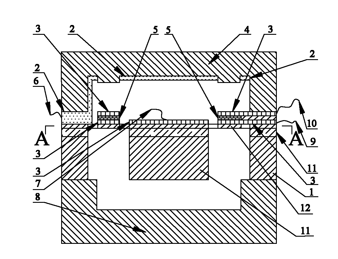
[0069] see Figure 1~3 , the piezoelectric-electrostatic composite micromechanical vibration energy harvester of the present invention is provided with a chip main body and an external circuit of the chip;

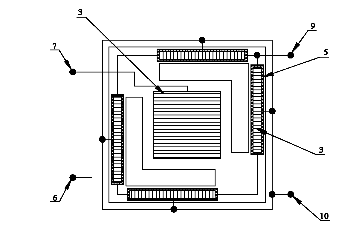
[0070] The main body is a three-layer sheet structure, with an upper glass sheet device 4, an SOI sheet device 1, a lower glass sheet device 8, a piezoelectric ceramic sheet group (composed of 4 piezoelectric ceramic sheets 5), piezoelectric ceramic sheet electrodes (there are 4 pairs of electrodes 3) and variable capacitance plate electrodes (1 pair of electrodes made up of upper electrode 2 and lower electrode 3).

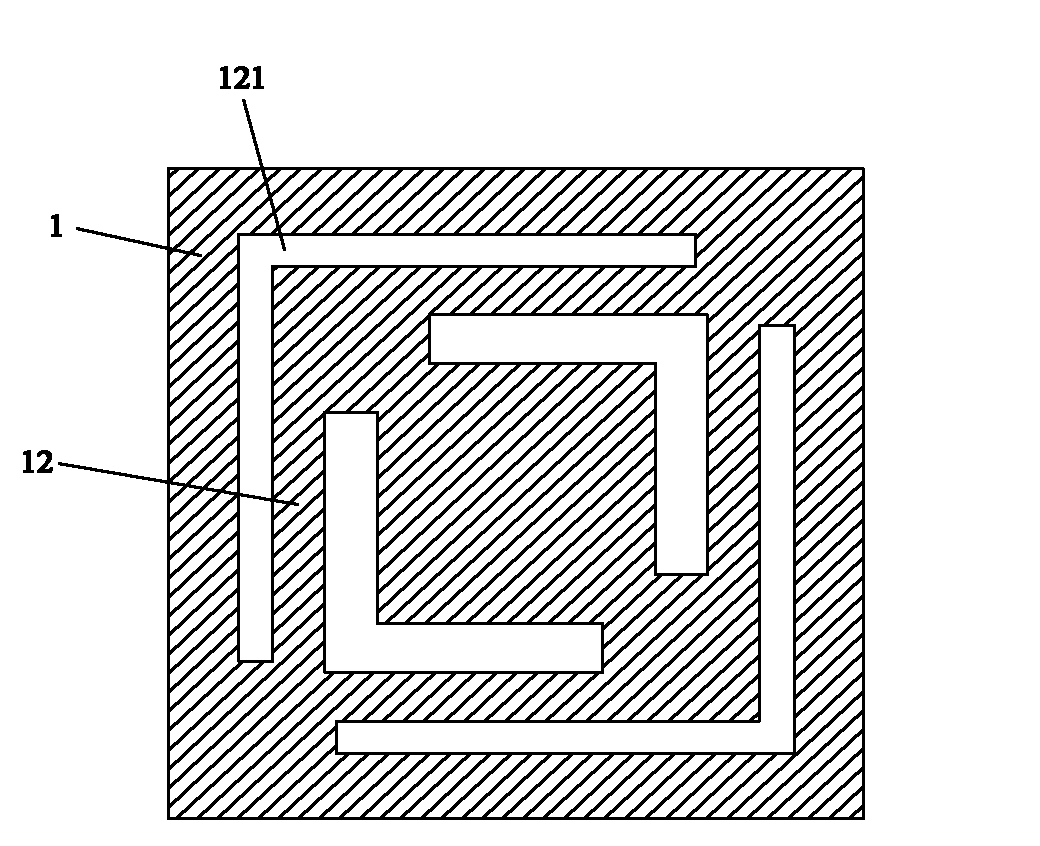
[0071] The cross-sectional shape of the upper glass sheet device 4 is an inverted U shape; the cross-sectional shape of the SOI sheet device 1 is an inverted mountain shape, and the middle part of the SOI sheet device 1 is a mass block 11, and the connecting portion 12 between the mass block 11 and the surrounding wall is set. There are four L-shaped hollow ...

Embodiment 2

[0112] see Figure 8 , similar to Embodiment 1, the only difference is that the external circuit of the chip is different. The external circuit of the chip is provided with a filter capacitor 14 (C), a first switch 15 (SW1), a second switch 17 (SW2), an energy storage capacitor 18 (C s ) and the variable capacitance plate start-up power supply 20; the output end of the variable capacitance plate start-up power supply 20 is connected to the variable capacitor 16 (C through the first switch 15 v ) plate electrode input terminal, the output terminal of the variable capacitor 16 plate electrode is connected to the input terminal of the energy storage capacitor 18 through the second switch 17, and the output terminal of the energy storage capacitor 18 is connected to an external load R. Both the first switch 15 and the second switch 17 are diode switches. The starting power supply 20 of the capacitor plate can directly adopt an external DC power supply, such as a battery or an ex...


PUM

PropertyMeasurementUnit
Thicknessaaaaaaaaaa
Thicknessaaaaaaaaaa
Depthaaaaaaaaaa

Abstract

The invention relates to a piezoelectric-static composite micro machine vibration energy collector and a manufacture method of the collector, and relates to an energy collecting device. The piezoelectric-static composite micro machine vibration energy collector comprises a chip main body and a chip external circuit, wherein the chip main body is of a three-layer laminated structure, and the chip main body comprises an upper glass piece device, an SOI (Silicon On Insulator) piece device, a lower glass piece device, a piezoelectric ceramic wafer device, a piezoelectric ceramic wafer electrode and a variable capacitance plate electrode. The chip external circuit is provided with a rectification circuit, a filter capacitor, a first switch, a second switch and an energy storage capacitor, or is provided with a rectification circuit, a filter capacitor, a first switch, a second switch and an energy storage capacitor and a variable capacitance plate starting power supply. The manufacture method comprises the following steps of: manufacturing the lower glass piece device; manufacturing the SOI piece device; manufacturing the upper glass piece device; assembling; and connecting the chip external circuit. According to the collector and the manufacture method, the process is simple, the defects of poorer device stability and performance and the like caused by,manufacturing a PZT (Piezoelectric Transducer) by using the traditional sol gel can be overcome, and wide band and high efficiency collection of energy can be realized.

Description

technical field [0001] The invention relates to an energy harvesting device, in particular to a piezoelectric-electrostatic composite micromechanical vibration energy harvester (chip type) and a manufacturing method thereof. Background technique [0002] With the expansion of sensor network functions, more and more micro-sensing systems are placed in special environments (such as the seabed, inside building walls, inside the human body, unattended places such as mountains or islands, etc.), At this time, the replacement of conventional batteries becomes extremely inconvenient, even impossible. Therefore, the lack of small size, high energy density, and long-life power supply has become a "bottleneck" restricting the practical application of micro-sensing systems. In order to solve this "bottleneck" problem, researchers have proposed the concept of "environmental energy harvesting", that is, collecting natural environmental energy (such as light energy, heat energy, electrom...

Claims


Application Information

Patent Timeline
IPC IPC(8): H02N2/18B81C1/00
Inventor 伞海生邓志强王翔赵山华
Owner XIAMEN UNIV
Why Eureka
Try Eureka