Integrated portable confocal opto-acoustic microscopy imaging device and method

A microscopic imaging, portable technology, applied in the direction of acoustic wave diagnosis, infrasonic wave diagnosis, ultrasonic/sonic wave/infrasonic wave diagnosis, etc., which can solve the problems that cannot be done

Active Publication Date: 2012-07-18
SOUTH CHINA NORMAL UNIVERSITY
View PDF3 Cites 35 Cited by
  • Summary
  • Abstract
  • Description
  • Claims
  • Application Information

AI Technical Summary

Problems solved by technology

At present, it is difficult for optical microscopes to go beyond the limitation of imaging depth, so it cannot achieve deep imaging in the body, while photoacoustics relies on absorption difference imaging, and combines the advantages of deep imaging depth of ultrasound and high contrast of optical imaging

Method used


Image

  • Integrated portable confocal opto-acoustic microscopy imaging device and method
  • Integrated portable confocal opto-acoustic microscopy imaging device and method
  • Integrated portable confocal opto-acoustic microscopy imaging device and method

Examples


Embodiment 1

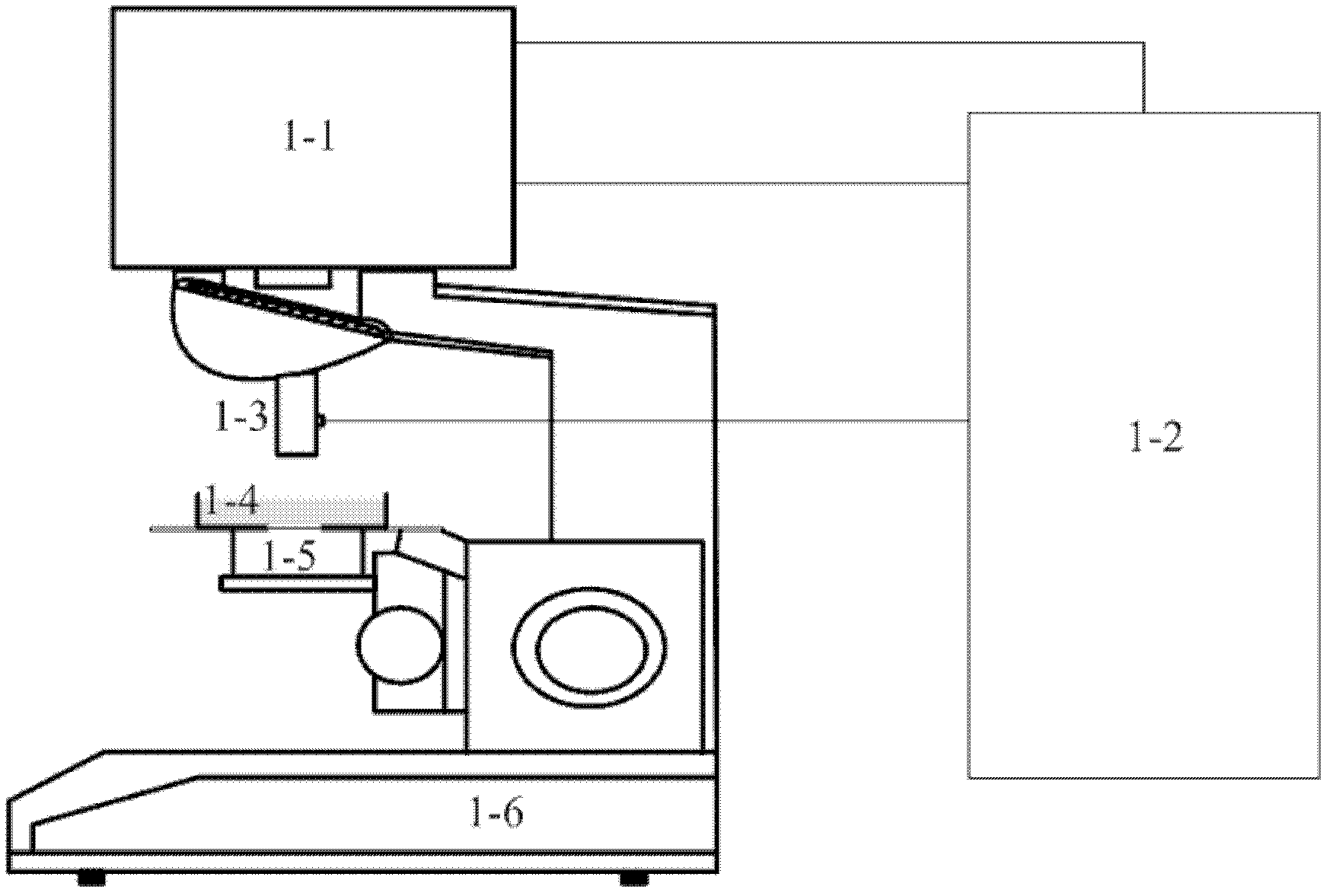
[0044] Integrated portable confocal photoacoustic microscopy imaging device, the structure diagram is as follows figure 1 shown.

[0045] The photoacoustic microscopic imaging device includes a scanning head 1-1, a computer 1-1 with a dual-channel parallel acquisition card (model NI5224, produced by National Instrument, USA) and an acquisition control and signal processing system (written by Labview software). 2. Acousto-optic confocal photoacoustic detectors 1-3, coupling slots 1-4, sample stages 1-5, instrument fixing / supporting devices 1-6. The coupling groove 1-4 and the sample stage 1-5 are integrated, and the height can be adjusted up and down as required.

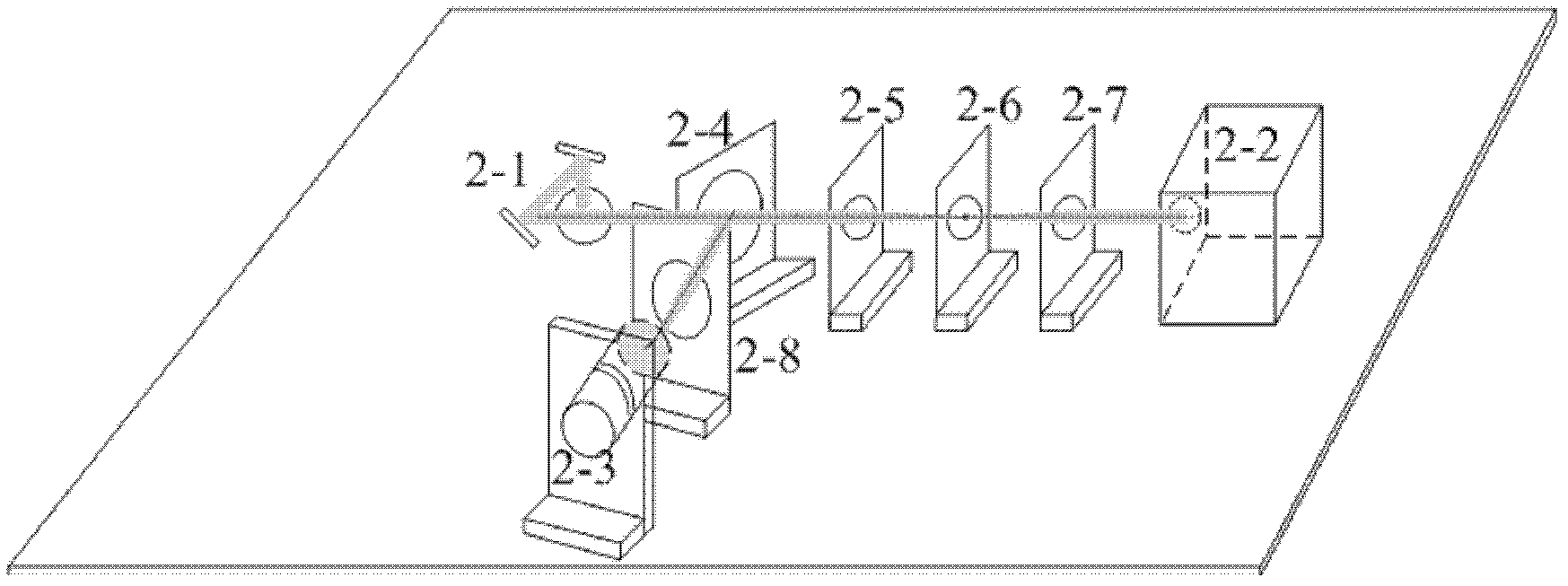
[0046] Among them, the scanning head 1-1 is composed of a photoacoustic excitation source and a miniature X-Y two-dimensional galvanometer (model 6231H, produced by Cambridge Technology) 2-1; and a microchip laser 2-2 (model HLX-I-F005, which is Horus Laser company's HLX-G series), lens 2-5, micro pinhole 2-6, and ...

Embodiment 3

[0058] The method of using the microscopic imaging device of Example 1 to perform in-body photoacoustic microscopy two-dimensional and three-dimensional imaging:

[0059] (1) A two-week-old Kunming mouse was injected with 0.5 mL of 2% pentobarbital sodium solution. After the mouse was anesthetized, the hair on the back surface of the mouse was removed with a depilatory cream for human use, and then the mouse was placed in a Place it on the sample stage and fix it. Add warm water at 37°C in the coupling tank as the coupling liquid, and monitor the water temperature with a thermometer to make the water temperature consistent with the temperature of the sample to be tested, that is, measure the water temperature regularly, and keep the water temperature consistent with the temperature of the sample to be tested in time. Adjust the sample stage to an appropriate height, so that the lower end of the hollow focused ultrasonic transducer in the acousto-optic confocal photoacoustic de...


PUM


Abstract

The invention belongs to the technical field of microscopy imaging, and discloses an integrated portable confocal opto-acoustic microscopy imaging device and a method. The imaging device comprises an opto-acoustic excitation light source, an acousto-optical confocal opto-acoustic detector, a photodiode, a miniature X-Y two-dimensional galvanometer, a spectroscope, a lens, a sample table, a double-channel parallel acquisition card and a computer with acquisition control software and two-dimensional galvanometer control software. The method includes steps that after the direction of laser light emitted from the opto-acoustic excitation light source is changed via the miniature X-Y two-dimensional galvanometer, the laser light is focused by the balsaming lens and irradiates on samples to excite opto-acoustic signals, the opto-acoustic signals are received by the acousto-optical confocal opto-acoustic detector, the incident angle of a light beam is continuously changed by the two-dimensional galvanometer so that the samples are scanned, and finally, an opto-acoustic image is rebuilt by maximum projection algorithm. A micro-chip laser device and the miniature X-Y two-dimensional galvanometer are integrated to form the portable confocal opto-acoustic microscopy imaging device, mobility is good, imaging speed is fast, and resolution ratio and contrast ratio are high.

Description

technical field [0001] The invention belongs to the technical field of microscopic imaging, and in particular relates to an integrated portable confocal photoacoustic microscopic imaging method and device. Background technique [0002] When a certain absorber is irradiated with light, the absorber absorbs the light energy and produces a temperature rise, and the temperature rise and fall causes the volume of the absorber to expand and shrink, and ultrasonic waves are generated. This phenomenon is called the photoacoustic effect. The photoacoustic effect has attracted people's attention since it was discovered in the 19th century, and it has been applied in various fields to varying degrees. As a new imaging technology, photoacoustic imaging has been applied in more and more fields. This imaging technology uses short-pulse laser as the excitation source, and the ultrasonic signal excited by it as the information carrier. By reconstructing the image of the collected signal, t...

Claims


Application Information

Patent Timeline
Patent Type & Authority Applications(China)
IPC IPC(8): A61B8/00A61B5/00
Inventor 邢达陈重江袁毅杨思华
Owner SOUTH CHINA NORMAL UNIVERSITY
Why Eureka
Try Eureka