Photocatalysis reduction method and device for CO2 in flue gas in oxygen-enriched combustion power plant

A photocatalytic and CO2 technology, applied in chemical instruments and methods, separation methods, air quality improvement, etc., can solve the problems of inability to utilize resources, environmental hazards, high cost, etc., and achieve low resistance, reduce CO2 emissions, and low cost Effect

Active Publication Date: 2014-06-18
HUAZHONG UNIV OF SCI & TECH
View PDF2 Cites 0 Cited by
  • Summary
  • Abstract
  • Description
  • Claims
  • Application Information

AI Technical Summary

Problems solved by technology

The first two types of technologies often have disadvantages such as high energy consumption, high cost, and possible harm to the environment.
Although the current oxygen-enriched combustion technology can realize the reduction of CO in coal-fired flue gas 2 Large-scale capture, but unable to capture CO in flue gas 2 Make resource utilization

Method used


Image

  • Photocatalysis reduction method and device for CO2 in flue gas in oxygen-enriched combustion power plant
  • Photocatalysis reduction method and device for CO2 in flue gas in oxygen-enriched combustion power plant
  • Photocatalysis reduction method and device for CO2 in flue gas in oxygen-enriched combustion power plant

Examples


Embodiment Construction

[0019] Below in conjunction with specific embodiment, further illustrate the present invention.

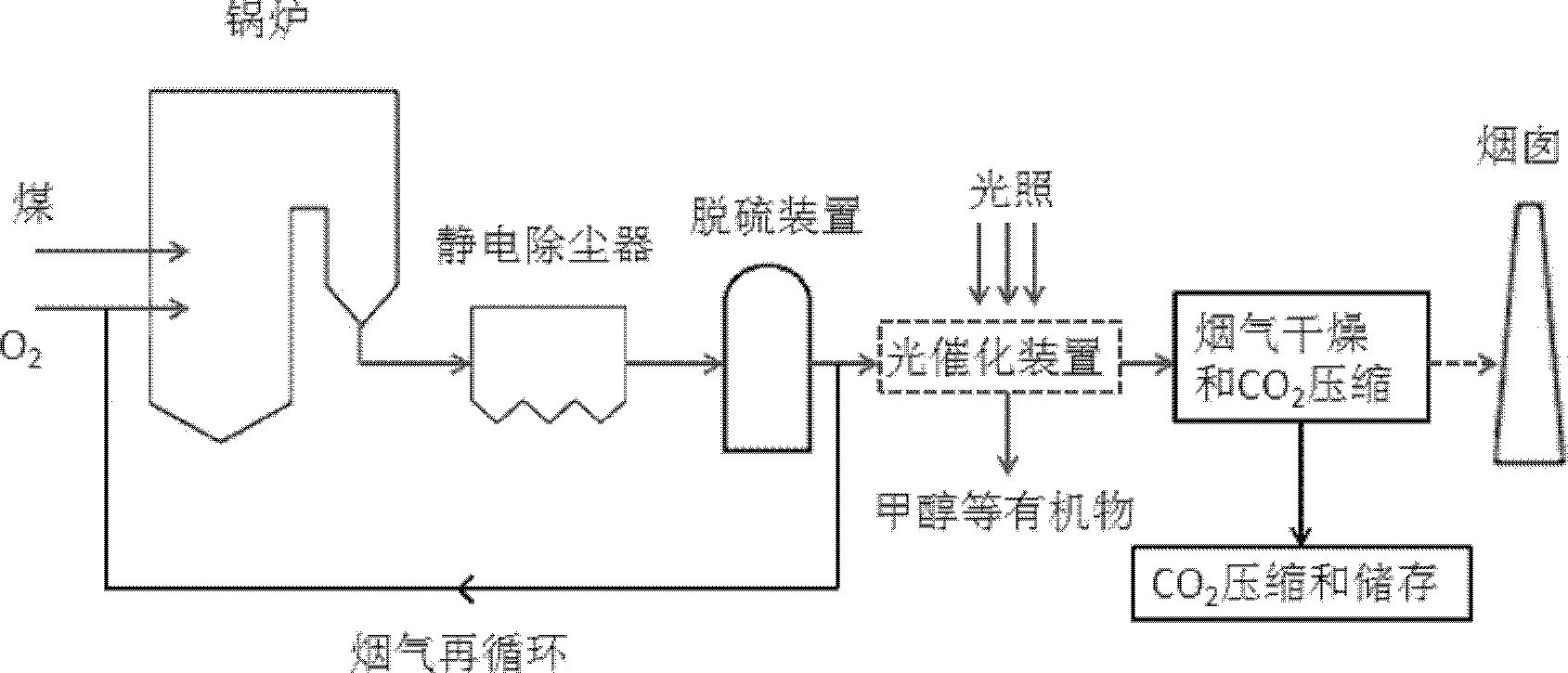
[0020] Such as figure 1 , flue gas drying and CO 2 Before the compression device, set a device that can reduce the high concentration of CO in the flue gas 2 A photocatalytic device for reducing organic substances such as methanol.

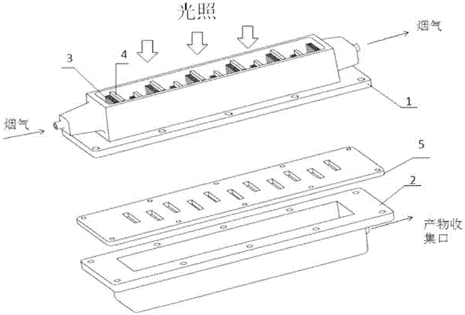
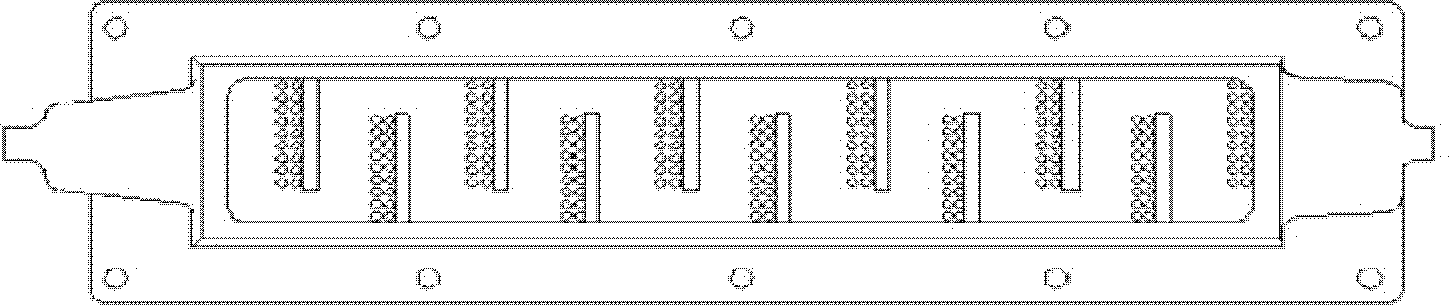
[0021] Such as figure 2 , a fiber optic photocatalytic device includes a reaction unit 1 and a product collection unit 2 . The reaction unit 1 includes a reaction chamber, the two ends of the reaction chamber are respectively provided with flue gas inlet and outlet, and the inside of the reaction chamber is equidistantly provided with a plurality of baffles 4 (see image 3 ), the optical fiber bundle 3 is arranged on the baffle plate 4 in a layered manner through the optical fiber holder, and the surface of each optical fiber is loaded with catalyst rare earth doped TiO 2 . The light source is injected from one end of the optical fiber layer th...


PUM


Abstract

The invention provides a photocatalysis reduction method for CO2 in flue gas in an oxygen-enriched combustion power plant, which specifically comprises the following steps of: carrying out photocatalysis reduction reaction of CO2 in flue gas between the flue gas desulfurization and the CO2 compression in the oxygen-enriched combustion power plant, and collecting liquid products obtained by reduction reaction. The invention further provides a reduction device which comprises a reaction unit, a product collecting unit and a clapboard; the reaction unit comprises a reaction chamber, wherein two ends of the reaction chamber are respectively provided with a flue gas inlet and a flue gas outlet, the reaction chamber is internally provided with a plurality of baffle plates at intervals, gas channels are formed between the baffle plates and the wall of the reaction chamber, catalyst-loaded optical fiber bundles are fixed on the baffle plates, and the top end of the reaction chamber is provided with a quartz glass plate cover plate; and the product collecting unit comprises a collecting chamber arranged under the reaction chamber, the clapboard is arranged between the reaction chamber and the collecting chamber, and holes are arranged on the positions of the clapboard, which are in one-to-one corresponding to the optical fiber bundles. According to the invention, the CO2 emission reduction and the resource utilization can be realized, and the method and the device are higher in CO2 treatment capability, low in cost, free of pollution, and low in energy consumption.

Description

technical field [0001] The invention provides a method for reducing high-concentration CO in the flue gas of a coal-based oxygen-enriched combustion power plant 2 Reduction method and device, especially a fiber-optic photocatalytic reduction of CO in the flue gas of an oxygen-rich combustion power plant using a rare earth-loaded modified titanium dioxide film 2 method and device. Background technique [0002] Greenhouse gases such as CO 2 、CH 4 The greenhouse effect caused by such emissions has become a global focus. In recent years, due to human production activities, atmospheric CO 2 Increased concentrations have accelerated the impact of the greenhouse effect on the global climate. How to effectively control CO 2 Emissions have become a national imperative. Since coal is the most important primary energy source in China, my country's CO 2 The emissions are mainly from coal combustion, among which coal-fired power plants are the main ones. Find an effective way to...

Claims


Application Information

Patent Timeline
Patent Type & Authority Patents(China)
IPC IPC(8): B01D53/88B01D53/62
CPCY02A50/20
Inventor 赵永椿熊卓张军营田冲郑楚光
Owner HUAZHONG UNIV OF SCI & TECH
Why Eureka
Try Eureka