Machining method of micro-drop and micro-fluidic control chip

A microfluidic chip and microdroplet technology, applied in chemical instruments and methods, laboratory containers, laboratory utensils, etc., can solve the problems of fragile, non-light-transmitting surface chemical behavior, and high bonding rejection rate. , to increase flexibility and diversity, facilitate observation and manipulation, and resist corrosion by organic solvents

Inactive Publication Date: 2012-07-18
TSINGHUA UNIV
View PDF3 Cites 16 Cited by
  • Summary
  • Abstract
  • Description
  • Claims
  • Application Information

AI Technical Summary

Problems solved by technology

The first type of material is monocrystalline silicon, which has a mature processing technology, but is fragile, expensive, opaque and has complex surface chemical behaviors.
The second type of material is an organic polymer, which can obtain channels with a large aspect ratio by casting or laser engraving, but it is not resistant to high temperature and organic solution corrosion, and it is not eas

Method used


Image

  • Machining method of micro-drop and micro-fluidic control chip
  • Machining method of micro-drop and micro-fluidic control chip
  • Machining method of micro-drop and micro-fluidic control chip

Examples


Example Embodiment

[0030] Example 1. Fabrication of T-shaped micro-droplet microfluidic chip
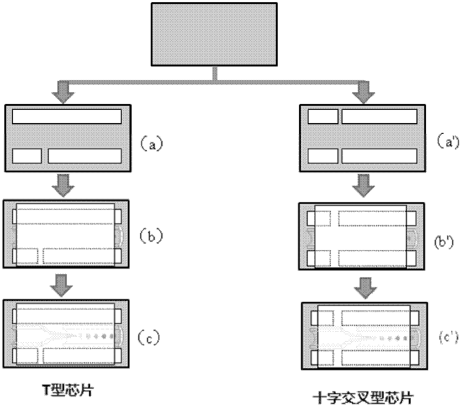
[0031] The process flow chart produced in this embodiment is as figure 1 Shown.

[0032] (1) Design the channel structure of the micro-droplet microfluidic chip as a T-shaped channel;

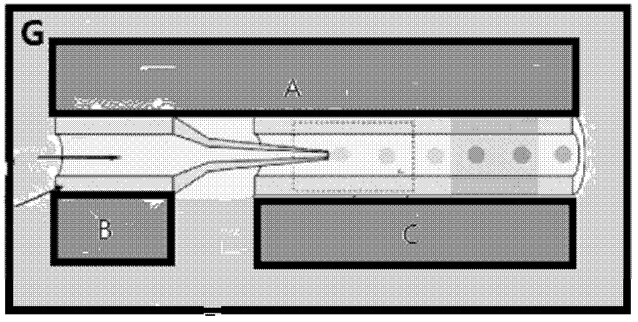
[0033] (2) According to the designed T-shaped channel, use a glass knife to cut out the required specifications and size of the component glass sheets A, B and C on the quartz glass slide;

[0034] (3) Build the designed T-shaped channel on the quartz glass substrate with the glass sheets A, B and C of each component, such as figure 1 As shown in (a); in the microchannel of the T-shaped channel, a cylindrical glass capillary with a tapered tail and a cylindrical glass capillary with the same inner and outer diameters are set, which has a tapered tail The tapered end of the cylindrical glass capillary tube is inserted into the cylindrical glass capillary tube and is arranged coaxially. The diameter of the tapered port of the cyl...

Example Embodiment

[0037] Example 2. Fabrication of cross-shaped micro-droplet microfluidic chip

[0038] The process flow chart produced in this embodiment is as figure 1 Shown.

[0039] (1) Design the channel structure of the micro-droplet microfluidic chip as a cross-shaped channel;
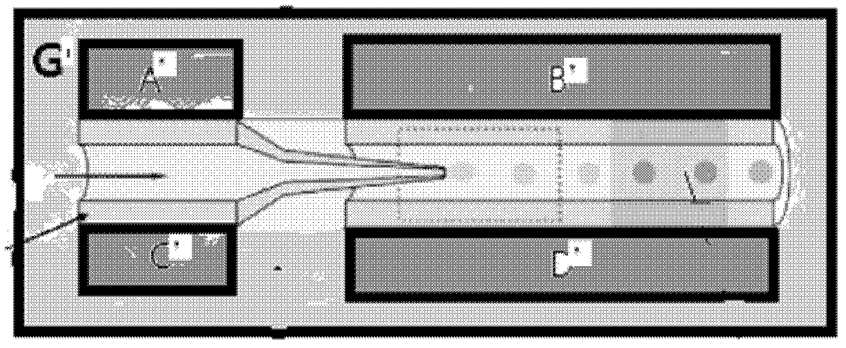
[0040] (2) According to the designed cross-shaped channel, use a glass knife to cut the required specifications and sizes of the component glass sheets A’, B’, C’ and D’ on the glass slide made of borosilicate glass;

[0041] (3) Build the designed T-shaped channel on the substrate made of borosilicate glass with the glass sheets A’, B’, C’ and D’ of each component, such as figure 1 As shown in (a'); a cylindrical glass capillary with a tapered tail and a cylindrical glass capillary with a tapered tail and a cylindrical glass capillary with the same inner diameter and outer diameter are arranged in the microchannel of the cross-shaped channel. The tapered end of the cylindrical glass capillary tube with a tapered tail i...


PUM

PropertyMeasurementUnit
Diameteraaaaaaaaaa
Diameteraaaaaaaaaa
Diameteraaaaaaaaaa

Abstract

The invention discloses a machining method of a micro-drop and micro-fluidic control chip. The method comprises the following steps: (1) designing and prefabricating a channel structure of the micro-drop and micro-fluidic control chip; (2) cutting component sheet glasses matched with the channel structure on a glass slide; (3) constructing the channel structure on a substrate by the component sheet glass; arranging a cylindrical glass capillary tube with a tapering tail spine and a cylindrical capillary tube in a microchannel of the channel structure, inserting the tail spine of the cylindrical glass capillary tube with the tapering tail spine into the cylindrical glass capillary tube and coaxially arranging the cylindrical glass capillary tube and the tail spine; and then linking a cover glass; and (4) inserting a plain end of the cylindrical capillary tube with the tapering tail spine into a thin tube with the inner diameter matched with that of the cylindrical capillary tube, and then inserting the thin tube into a gas between the component sheet glasses. According to the machining method, the process technology of the micro-drop and micro-fluidic control chip does not adopt a traditional etching method, so that the complicated processes such as photoetching can be avoided, the related expensive equipment can be omitted, and the dependence on professionals for MEMS (Micro Electro Mechanical System) can be abandoned.

Description

technical field [0001] The invention relates to a method for manufacturing a micro-droplet microfluidic chip, and belongs to the technical field of microfluidic chip manufacturing. Background technique [0002] At present, the development of microfluidic chips is mainly limited by chip materials, processing technology, molding methods and sealing processes. Chip materials are mainly divided into three categories. The first type of material is monocrystalline silicon, which has a mature processing technology, but is fragile, expensive, opaque and has complex surface chemical behaviors. The second type of material is an organic polymer, which can obtain channels with a large aspect ratio by casting or laser engraving, but it is not resistant to high temperature and organic solution corrosion, and it is not easy to modify the surface. The third type of material is glass, which has stable surface properties, is resistant to organic solvent corrosion, is not easy to absorb samp...

Claims


Application Information

Patent Timeline
IPC IPC(8): B01L3/00
Inventor 严清峰王秀瑜
Owner TSINGHUA UNIV
Why Eureka
Try Eureka