Fluidized bed reactor and method for methanation of gas mixture containing H2 and CO

A fluidized bed reactor, methanation technology

Active Publication Date: 2012-07-25
INST OF PROCESS ENG CHINESE ACAD OF SCI
View PDF17 Cites 23 Cited by
  • Summary
  • Abstract
  • Description
  • Claims
  • Application Information

AI Technical Summary

Problems solved by technology

[0013] Aiming at the problems of the removal of reaction heat in the methanation fluidized bed process and the uneven axial and radial distribution of the gas-solid flow in the fluidized bed, the present invention proposes a novel methanation multi-stage fluidized bed reaction The device and method are an integrated method for stabilizing the heat balance of the methanation fluidized bed process and uniformly distributing the particle concentration in the bed layer in the axial and radial directions. The method can improve heat exchange efficiency, efficiently recover reaction heat, and simplify the process. process, increasing device capacity

Method used


Image

  • Fluidized bed reactor and method for methanation of gas mixture containing H2 and CO
  • Fluidized bed reactor and method for methanation of gas mixture containing H2 and CO
  • Fluidized bed reactor and method for methanation of gas mixture containing H2 and CO

Examples


Embodiment 1

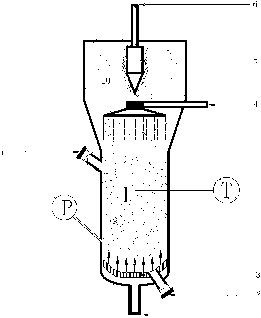
[0050] Specific implementation steps, such as figure 1 H 2 Schematic diagram of a fluidized bed reactor for catalytic methanation with CO mixed gas, the core of which is the raw material inlet 1, the catalyst outlet 2, the gas distribution plate 3, the cooling water spray device 4, the cyclone separator 5, and the catalyst inlet 7 , and the product gas outlet 6 are sequentially connected with the cylinder wall of the fluidized bed to form a complete single-stage fluidized bed. The height of the catalyst dense-phase zone of the single-stage fluidized bed is 4.0 times the diameter of the dense-phase zone. Use 20-40 meshes of alumina-supported nickel-based methanation catalyst (Ni content is 40%), and add the catalyst from the catalyst inlet 7. In order to avoid the catalyst from clogging the gas distribution plate 3, the catalyst is added from the raw material inlet at the bottom of the fluidized bed. 1 Nitrogen gas is passed through the gas distribution plate 3, and the cataly...

Embodiment 2

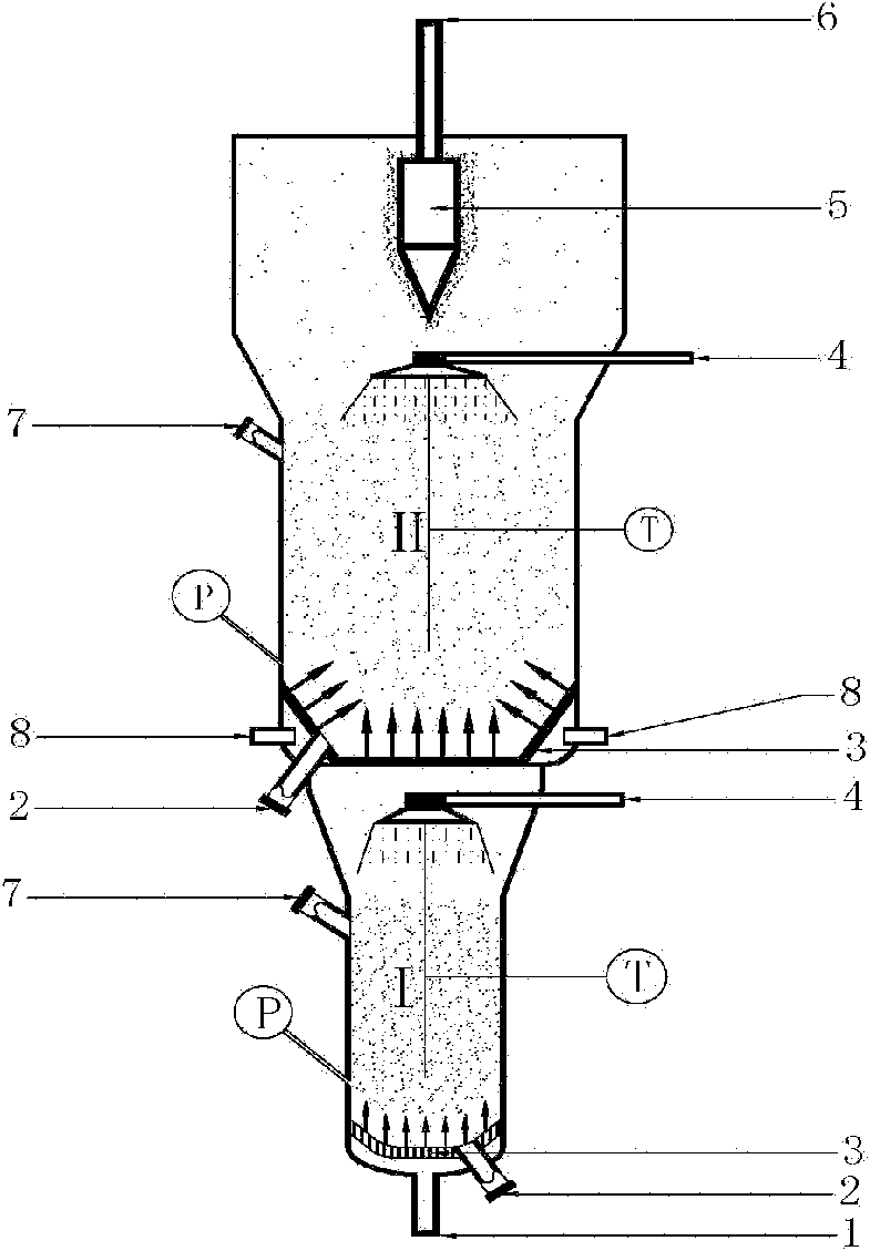
[0052] Specific implementation steps, such as figure 2The schematic diagram of the two-stage fluidized bed reactor for syngas methanation is shown, the core of which is the feed gas inlet 1, the gas distribution plate 3, the cyclone separator 5, the catalyst inlet 7, the catalyst outlet 2, the tube wall The raw material gas side line inlet 8 and the product gas outlet 6 are sequentially connected with the cylinder wall of the fluidized bed reactor to form a complete two-stage fluidized bed reactor. In this reactor, the distance between the gas distribution plate in the II reaction zone and the gas distribution plate in the first section is 8.0 times of the diameter of the dense-phase area of ​​the catalyst in the first section, while the diameter of the dense-phase area of ​​the catalyst in the second section is It is 2.0 times the diameter of the dense-phase zone of the first stage. A nickel-based methanation catalyst (Ni content is 40%) with a particle size of 20-40 meshes...

Embodiment 3

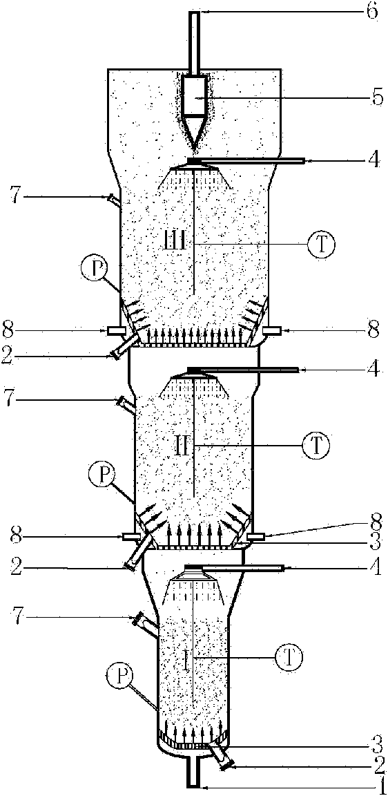
[0054] Specific implementation steps, such as image 3 The schematic diagram of the three-stage fluidized bed reactor for the methanation of raw material gas is provided as shown, the core of which is the raw material inlet 1, gas distribution plate 3, cyclone separator 5, catalyst inlet 7, catalyst outlet 2, tube wall The raw material gas side line inlet 8 and the gas outlet 6 are sequentially connected with the cylinder wall of the fluidized bed reactor to form a complete three-stage fluidized bed. The distance between the gas distribution plate in the third stage reaction zone and the gas distribution plate in the second stage in this fluidized bed reactor is 3.0 times of the diameter of the dense phase zone of the catalyst in the second stage, and the catalyst in the third stage The diameter of the dense-phase zone is 2.5 times the diameter of the dense-phase zone of the second stage; the distance between the gas distribution plate in the dense-phase zone of the second sta...


PUM


Abstract

The invention relates to a fluidized bed reactor and a method for methanation of gas mixture containing H2 and CO. The fluidized bed reactor of the invention comprises a material gas inlet 1, a catalyst outlet 2, a gas-solid separator 5, a product gas outlet 6, a catalyst inlet 7 and a material gas lateral line inlet, wherein one or more gas distribution plate 3 is arranged in the fluidized bed reactor in order to divide the reactor into several fluidized bed layers to form several catalyst dense-phase zones; a cooling water spraying device 4 is arranged above each layer of the catalyst dense-phase zone in order to control temperature of the reactor. Because the circulating cooling water directly contacts high-temperature product gas, the reactor of the invention strengthens heat transfer, is easy to control reaction temperature, reduces heat loss during the heat transfer and improves heat utilization rate during the reaction. The reactor has the advantages of large production flux, big operation elasticity, high CO conversion rate, high selectivity of produced methane, less catalyst dosage, high utilization rate of heat quantity and so on, so that the reactor has good industrial application prospect.

Description

technical field [0001] The invention relates to the field of methane production, in particular, the invention relates to a method for 2 Methanation fluidized bed reactor and method for mixed gas with CO. Background technique [0002] my country's energy characteristics of "rich in coal, short of oil, and low in gas" determine that the current situation of using coal as the main primary energy is difficult to change in the short term. About 85% of my country's current coal consumption is directly converted through combustion or gasification, and the proportion of direct combustion is as high as 80%. Or the synthesis gas obtained from biomass gasification (mainly containing H 2 , CO and CO 2 ) undergoes methanation to generate CH 4 , can increase the heat density of gas, reduce coal transportation power consumption and storage and transportation equipment investment, and at the same time provide a practical way to fill the gap in my country's natural gas demand, with high e...

Claims


Application Information

Patent Timeline
Patent Type & Authority Applications(China)
IPC IPC(8): B01J8/24C07C1/04C07C9/04
Inventor 苏发兵高加俭古芳娜王莹利翟世辉许光文
Owner INST OF PROCESS ENG CHINESE ACAD OF SCI
Why Eureka
Try Eureka