Fluidized bed reactor and method for methanation of gas mixture containing H2 and CO
A fluidized bed reactor, methanation technology, applied in chemical instruments and methods, organic chemistry, hydrocarbon production from carbon oxides, etc., can solve the problem of uneven distribution in the overall axial and radial directions, and improve the conversion of CO High efficiency, improved heat transfer efficiency, and uniform temperature
- Summary
- Abstract
- Description
- Claims
- Application Information
AI Technical Summary
Problems solved by technology
Method used
Image
Examples
Embodiment 1
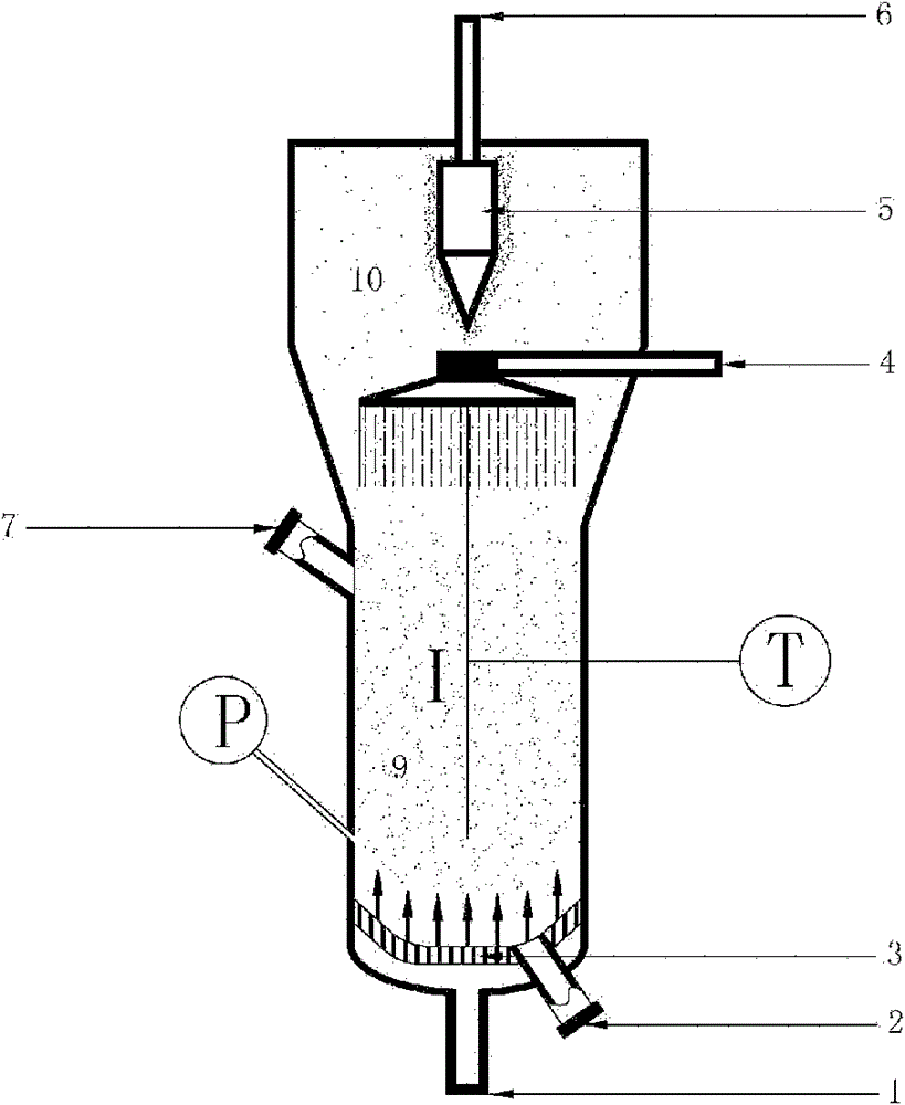
[0050] Specific implementation steps, such as figure 1 H 2 Schematic diagram of a fluidized bed reactor for catalytic methanation with CO mixed gas, the core of which is the raw material inlet 1, the catalyst outlet 2, the gas distribution plate 3, the cooling water spray device 4, the cyclone separator 5, and the catalyst inlet 7 , and the product gas outlet 6 are sequentially connected with the cylinder wall of the fluidized bed to form a complete single-stage fluidized bed. The height of the catalyst dense-phase zone of the single-stage fluidized bed is 4.0 times the diameter of the dense-phase zone. Use 20-40 meshes of alumina-supported nickel-based methanation catalyst (Ni content is 40%), and add the catalyst from the catalyst inlet 7. In order to avoid the catalyst from clogging the gas distribution plate 3, the catalyst is added from the raw material inlet at the bottom of the fluidized bed. 1 Nitrogen gas is passed through the gas distribution plate 3, and the cataly...
Embodiment 2
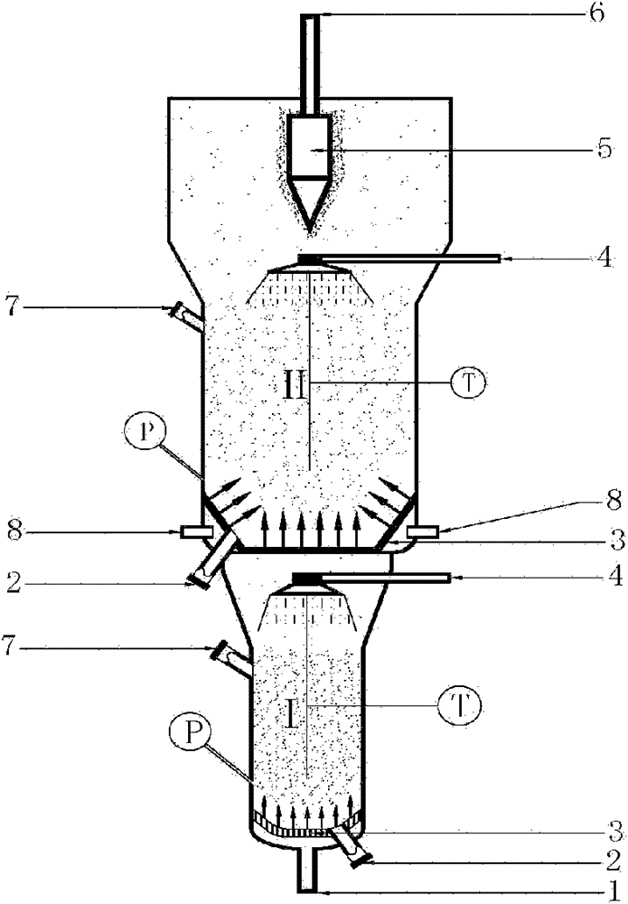
[0052] Specific implementation steps, such as figure 2The schematic diagram of the two-stage fluidized bed reactor for syngas methanation is shown, the core of which is the feed gas inlet 1, the gas distribution plate 3, the cyclone separator 5, the catalyst inlet 7, the catalyst outlet 2, the tube wall The raw material gas side line inlet 8 and the product gas outlet 6 are sequentially connected with the cylinder wall of the fluidized bed reactor to form a complete two-stage fluidized bed reactor. In this reactor, the distance between the gas distribution plate in the II reaction zone and the gas distribution plate in the first section is 8.0 times of the diameter of the dense-phase area of the catalyst in the first section, while the diameter of the dense-phase area of the catalyst in the second section is It is 2.0 times the diameter of the dense-phase zone of the first stage. A nickel-based methanation catalyst (Ni content is 40%) with a particle size of 20-40 meshes...
Embodiment 3
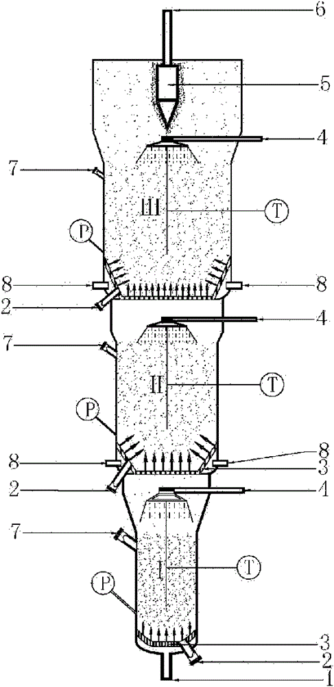
[0054] Specific implementation steps, such as image 3 The schematic diagram of the three-stage fluidized bed reactor for the methanation of raw material gas is provided as shown, the core of which is the raw material inlet 1, gas distribution plate 3, cyclone separator 5, catalyst inlet 7, catalyst outlet 2, tube wall The raw material gas side line inlet 8 and the gas outlet 6 are sequentially connected with the cylinder wall of the fluidized bed reactor to form a complete three-stage fluidized bed. The distance between the gas distribution plate in the third stage reaction zone and the gas distribution plate in the second stage in this fluidized bed reactor is 3.0 times of the diameter of the dense phase zone of the catalyst in the second stage, and the catalyst in the third stage The diameter of the dense-phase zone is 2.5 times the diameter of the dense-phase zone of the second stage; the distance between the gas distribution plate in the dense-phase zone of the second sta...
PUM
 Abstract
Description
Claims
Application Information
 - R&D
- Intellectual Property
- Life Sciences
- Materials
- Tech Scout
- Unparalleled Data Quality
- Higher Quality Content
- 60% Fewer Hallucinations
Browse by: Latest US Patents, China's latest patents, Technical Efficacy Thesaurus, Application Domain, Technology Topic, Popular Technical Reports.
© 2025 PatSnap. All rights reserved.Legal|Privacy policy|Modern Slavery Act Transparency Statement|Sitemap|About US| Contact US: help@patsnap.com


