
Magnetic valve type controllable electric reactor control system and control method

A control system and reactor technology, applied in the direction of variable inductance/transformer, transformer/inductor coil/winding/connection, circuit, etc., can solve the problems of partial discharge, slow control speed, overheating of iron fuel tank cover, etc. , to achieve the effect of preventing phenomenon and sampling aliasing

Inactive Publication Date: 2012-07-25
STATE GRID CORP OF CHINA +1
View PDF5 Cites 7 Cited by
  • Summary
  • Abstract
  • Description
  • Claims
  • Application Information

AI Technical Summary

Problems solved by technology

[0016] 1. The existing reactor adopts an iron fuel tank, and the magnetic flux leakage is relatively large during operation. The wall of the fuel tank will generate eddy current loss. If necessary, magnetic shielding must be added to the tank wall, resulting in an increase in the volume of the fuel tank
[0017] 2. Secondly, the top outlet of the existing reactor adopts the outlet column, and the iron fuel tank needs to use two 72kV high-voltage bushings, so that the height of the fuel tank increases
Uneven field strength, easy to cause partial discharge
[0018] 3. Due to the existence of magnetic flux leakage during operation, the bottom and cover of the iron fuel tank are overheated
[0019] 4. The installation of the thyristor is usually installed outside the reactor, and the reactor is large in size, which puts forward higher and more requirements for the site and insulation, and also increases the installation workload
[0020] 5. In reality, there are many analytical works on reactors in theory, but few are actually put into practice, especially in the fields of high voltage or extra high voltage and fields with higher requirements for insulation.
[0021] 6. In terms of controllers, the MCR controllers researched and produced by most domestic manufacturers mostly use 80C196 as the core, which has disadvantages such as slow control speed, insufficient sampling accuracy, and unfriendly man-machine interface, which seriously restricts the performance and performance of MCR. product promotion
In addition, because the application of MCR is a relatively new technology in the world, it is still in the theoretical stage or trial operation stage in China, and has not yet been carried out on a large scale. As a result, my country is still immature in terms of implementation technology
[0022] 7. In reality, the reactor controller has a lot of analytical work in theory, and the design scheme in implementation is more complicated. Optical fiber communication is mostly used, the wiring is complicated, the maintenance procedures are cumbersome, and the requirements for operators are high, resulting in implementation and maintenance. It is more difficult, especially in the case of high-voltage or ultra-high-voltage fields that have high requirements for insulation, and few of them are actually put into practice

Method used


Image

  • Magnetic valve type controllable electric reactor control system and control method
  • Magnetic valve type controllable electric reactor control system and control method
  • Magnetic valve type controllable electric reactor control system and control method

Examples


Embodiment Construction

[0089] The present invention will be further described below in conjunction with the accompanying drawings and embodiments.

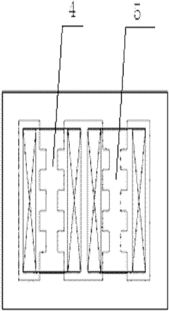
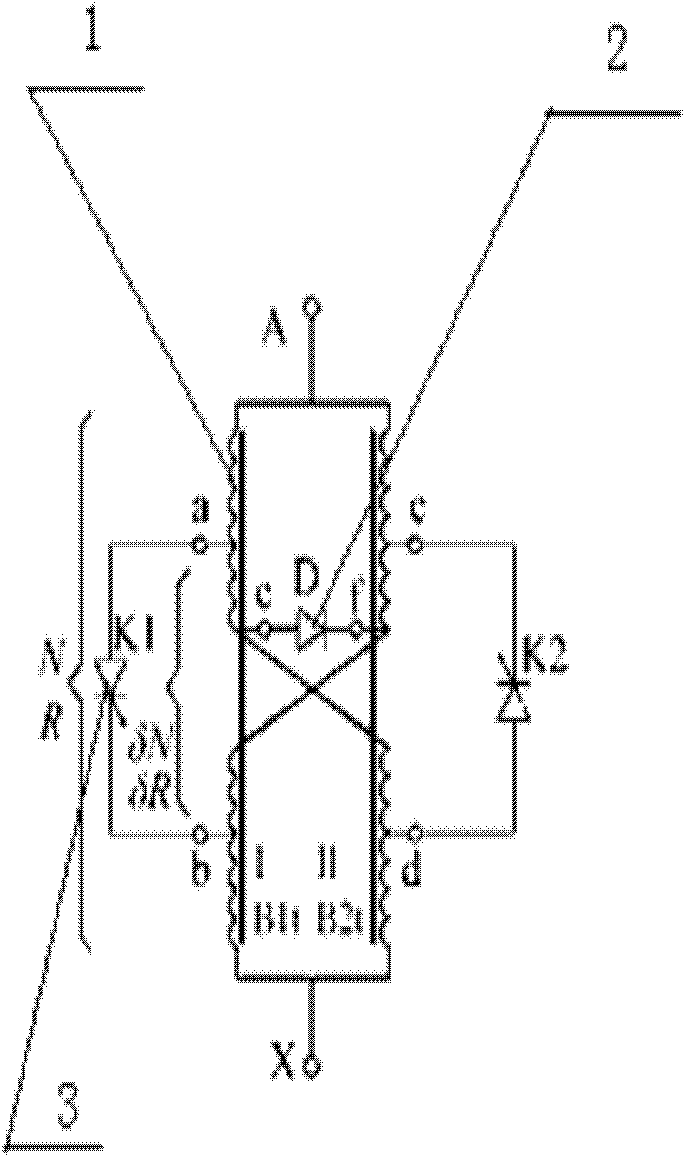
[0090] Figure 1A is a structural diagram of a single-phase MCR; Figure 1B is a schematic diagram of the principle of a single-phase MCR;

[0091] The magnetic valve type controllable reactor of the present invention has no side yoke structure, which constitutes a two iron core structure controllable reactor. The yoke constitutes a four-column iron core structure, and the iron core column I 4 and the iron core column II 5 are respectively provided with at least one small section section, and the upper and lower sides of the iron core column I 4 are symmetrically wound with coils A with the same number of turns 1. B. The upper and lower sides of the working iron core column II 5 are at least symmetrically wound with coils C and D with the same number of turns, and the number of turns of the coils A, B, C and D are all equal; the coils A, B, C, and D are ...


PUM

PropertyMeasurementUnit
heightaaaaaaaaaa

Abstract

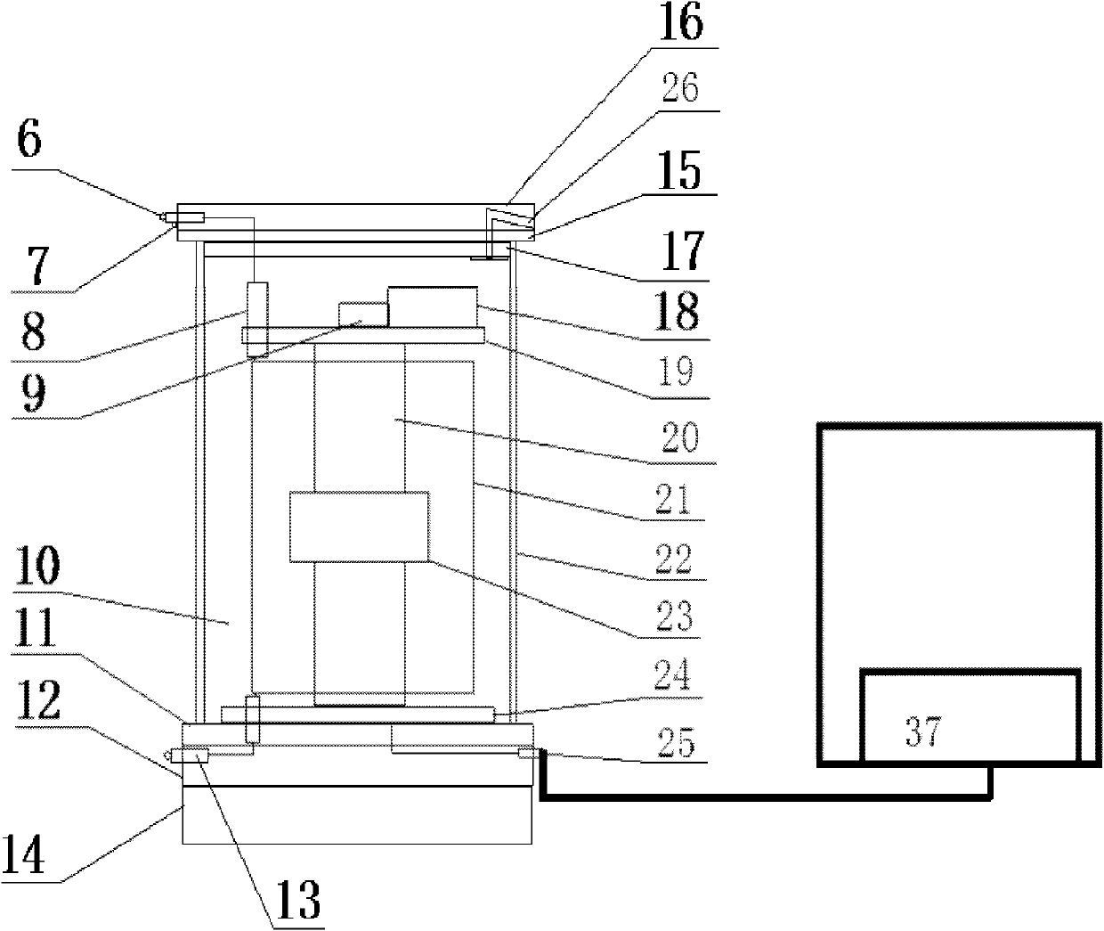
The invention discloses a magnetic valve type controllable electric reactor control system, which comprises an electric reactor and a controller, wherein the electric reactor comprises an outer insulation tube, the upper end of the outer insulating tube is provided with an upper end cover part, the lower end of the outer insulating tube is connected with a lower end cover part, the upper end cover part comprises an electric reactor high-voltage terminal and an upper end cover, the lower end cover part comprises an electric reactor low-voltage terminal, a pulse control wire terminal and a lower end cover, an electric reactor body is fixedly arranged on the inner surface of the lower end cover, the upper end of an electric reactor iron core is provided with an insulation support frame, a thyristor assembly and a pulse transformer are arranged on the insulation support frame, the pulse transformer is connected with the pulse control wire terminal, the controller comprises a controller body, and the controller body is connected with the pulse control wire terminal. The magnetic valve type controllable electric reactor control system has the beneficial effects that the manufacture process of the magnetic valve type controllable electric reactor control system is simple, the cost is low, the loss is small, the harmonic wave is small, and greater application potential is respectively realized in aspects of electric network transmission capacity improvement, electric network voltage regulation, reactive power compensation and overvoltage limitation.

Description

technical field [0001] The invention relates to an automatic control system for a reactor, in particular to a control system and a control method for a magnetic valve type controllable reactor. Background technique [0002] my country has a vast territory and uneven distribution of energy sources. "Power transmission from west to east and mutual supply from north to south" is the basic national policy for the development of my country's power system. This determines that my country's power system transmission network is huge, and there are a large number of long-distance transmission lines. Under the condition of a large power grid, how to safely and efficiently transport electric energy from the power plant to the load center where the power distribution system is located, how to provide users with high-quality electric energy, how to effectively reduce the pollution of reactive power to the power grid, and ensure the safety of the power grid Efficient operation has become...

Claims


Application Information

Patent Timeline
Patent Type & Authority Applications(China)
IPC IPC(8): H02P13/00H02J3/16H02J3/18H01F21/00H01F27/26H01F27/28H01F27/29H01F27/32
CPCY02E40/34Y02E40/30
Inventor 张凡华张连宏张勇贾传斌李万忠于洪李永宁谭京一林冬晧孙英涛周迎新杨琦欣仝瑞士
Owner STATE GRID CORP OF CHINA
Learn More