Power system for electrombile
A technology for power systems and electric vehicles, applied in the field of electric vehicles, can solve problems such as hidden safety hazards, shortened battery life, and alarming problems.
- Summary
- Abstract
- Description
- Claims
- Application Information
AI Technical Summary
Problems solved by technology
Method used
Image
Examples
Embodiment 1
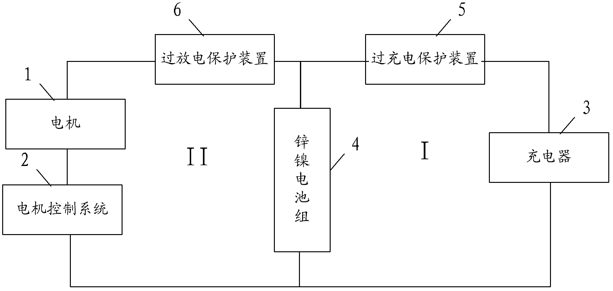
[0052] figure 1 It is a schematic structural diagram of the electric vehicle power system provided by the embodiment of the present application.
[0053] In the embodiment of the present application, the electric vehicle is provided with a motor 1 and a motor control system 2, and the motor 1 is used as a driving device for driving the wheels of the electric vehicle to provide power for the electric vehicle.
[0054] When charging electric vehicles, chargers are usually used, such as figure 1 As shown, 3 in the figure is a charger, and the main function of the charger 3 is to transform, rectify and filter the industrial power and input it into the battery pack on the electric vehicle to charge the battery pack.
[0055] Such as figure 1 As shown, the electric vehicle power system includes: a mounting bracket (not shown in the figure), a zinc-nickel battery pack 4 , an overcharge protection device 5 and an overdischarge protection device 6 .
[0056] In the embodiment of the...
Embodiment 2
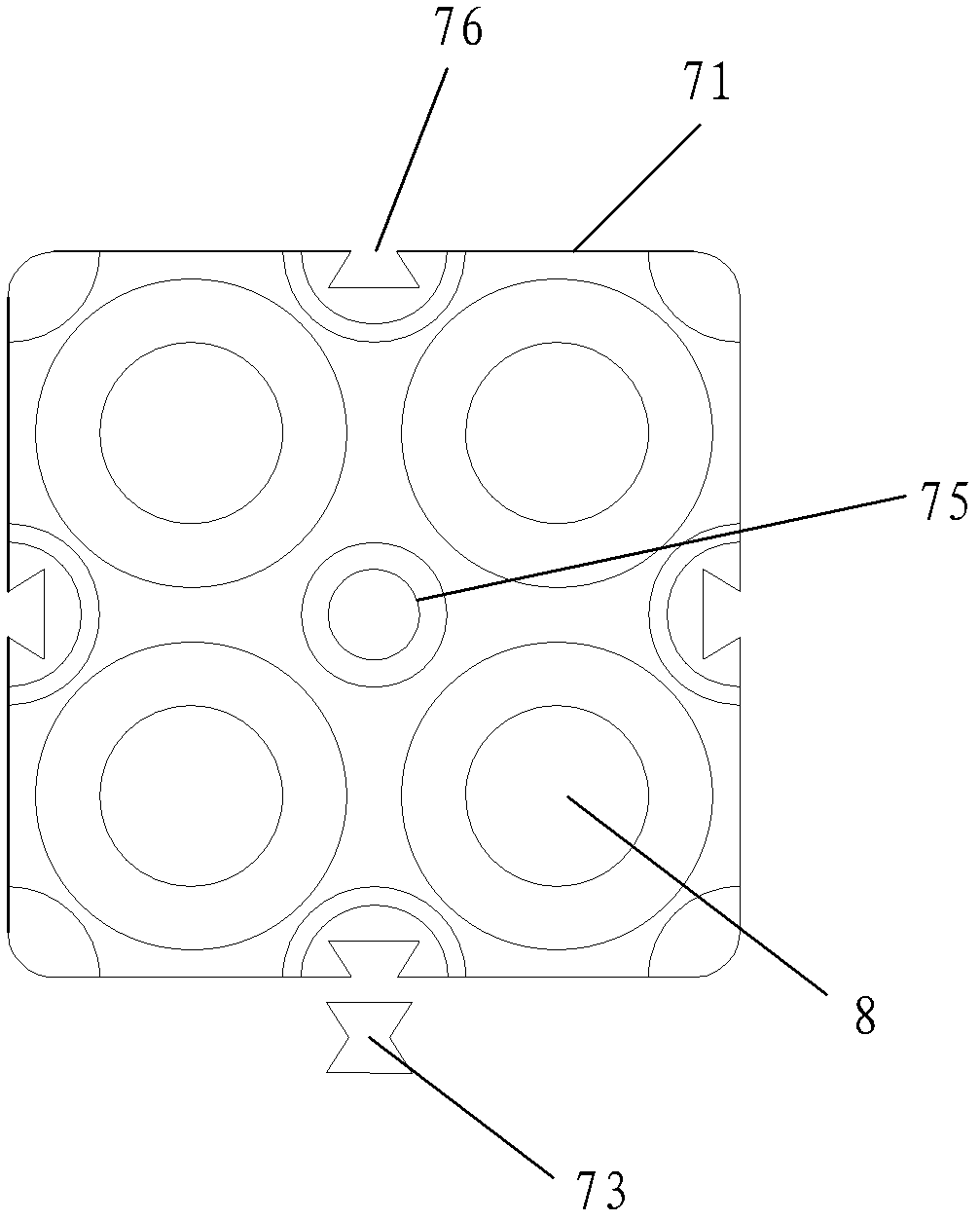
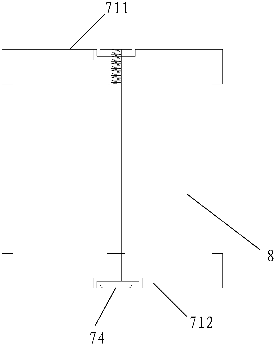
[0066] figure 2 It is a schematic top view structure diagram of the mounting bracket provided by the embodiment of the present application. image 3 It is a schematic side view structural diagram of the mounting bracket provided by the embodiment of the present application.
[0067] Such as figure 2 and image 3 As shown, the mounting bracket includes: a plurality of bracket bodies 71, a plurality of metal connecting pieces (not shown in the figure), dovetail fasteners 73 and fastening bolts 74, wherein:
[0068] Each bracket body 71 is composed of a top 711 and a bottom 712. The top 711 and the bottom 712 of the bracket body 71 are fastened together, and a plurality of spaces that can accommodate zinc-nickel battery cells are also provided inside the bracket body 71. Such as image 3 As shown, 8 in the figure is a zinc-nickel battery cell. The function of multiple metal connecting pieces is to connect multiple zinc-nickel battery cells 8 in series.
[0069] Such as ...
Embodiment 3
[0075] Figure 6 It is a schematic structural diagram of an overcharge protection device provided in an embodiment of the present application.
[0076] Such as Figure 6 As shown, the overcharge protection device 5 may include: a temperature acquisition unit 51 , a temperature comparison unit 52 , a first logic control unit 53 and a first electronic switch 54 .
[0077] The temperature acquisition unit 51 is arranged in the zinc-nickel battery pack 4 and is used for collecting temperature signals of the zinc-nickel battery pack 4 .
[0078] In the normal charging process, when the zinc-nickel battery cells in the zinc-nickel battery pack 4 are not overcharged, the overall temperature of the zinc-nickel battery pack 4 is relatively stable, and once a certain zinc-nickel battery cell is overcharged, Then it will cause the temperature of the whole zinc-nickel battery pack 4 to rise, so it is only necessary to set a temperature acquisition unit 51 in the zinc-nickel battery pack...
PUM
 Abstract
Description
Claims
Application Information
 - R&D
- Intellectual Property
- Life Sciences
- Materials
- Tech Scout
- Unparalleled Data Quality
- Higher Quality Content
- 60% Fewer Hallucinations
Browse by: Latest US Patents, China's latest patents, Technical Efficacy Thesaurus, Application Domain, Technology Topic, Popular Technical Reports.
© 2025 PatSnap. All rights reserved.Legal|Privacy policy|Modern Slavery Act Transparency Statement|Sitemap|About US| Contact US: help@patsnap.com


