4f phase imaging method for high sensitively measuring optical nonlinearity of material

A high-sensitivity measurement and optical nonlinear technology, which is applied in the field of optical nonlinear measurement of materials, can solve problems such as difficult to measure accurately and cannot meet the requirements of measurement, so as to improve the measurement sensitivity and solve the effect of easy damage

Active Publication Date: 2012-08-01
SUZHOU MICRONANO LASER PHOTON TECH CO LTD
2 Cites 10 Cited by

AI-Extracted Technical Summary

Problems solved by technology

However, when the nonlinear phase shift is small, due to the CCD image noise fluctuation and interference fringe modulation, it is dif...

Method used

I (r, t)=|E04t1(r)|2 (7) in the present embodiment, incident energy is 0.1 μ J, PO baffle plate center PO region radius Ri=0.6mm, annular region outer diameter Ra= 3mm, and the focal lengths of the convex lens 7 and the convex lens 10 are 412mm. Figure 5 shows the simulated radial light intensity...

Abstract

The invention discloses a 4f phase imaging method for high sensitively measuring optical nonlinearity of a material, and belongs to the nonlinear photonics material and nonlinear optical information processing field. The 4f phase imaging method comprises the following steps that a laser beam is accurately and straightly emitted to a polyolefin (PO) baffle plate, a 4f system and a ring-shaped attenuation sheet after being expanded, and an emergent facular is imaged on a charge coupled device (CCD); partial split beam passing through the PO baffle plate permeates a reflection mirror, a convex lens, a reflection mirror and a beam splitting lens to be imaged onto the CCD after being reflected by the beam splitting lens; a beam passing through the convex lens is focused onto a sample to be tested, so that the sample produces optical nonlinearity; the PO baffle plate and a CCD image sensor are respectively arranged on an object plane and an image plane of the 4f system, and the ring-shaped attenuation sheet is arranged to be close to the CCD image sensor; when phase difference of one-half phi is generated in the center of the PO baffle plate, the light intensity is simultaneously and linearly attenuated in a central PO area, and the rest ring-shaped facular is attenuated at the same proportion by the ring-shaped attenuation sheet. Due to the adoption of the 4f phase imaging method, attenuation of the background light and the signal light in different proportions can be realized, and the measurement sensitivity is greatly improved.

Application Domain

Material analysis by optical means

Technology Topic

Image sensorPhase imaging +16

Image

  • 4f phase imaging method for high sensitively measuring optical nonlinearity of material
  • 4f phase imaging method for high sensitively measuring optical nonlinearity of material
  • 4f phase imaging method for high sensitively measuring optical nonlinearity of material

Examples

  • Experimental program(1)

Example Embodiment

[0022] The present invention will be further described below in conjunction with the drawings and embodiments:
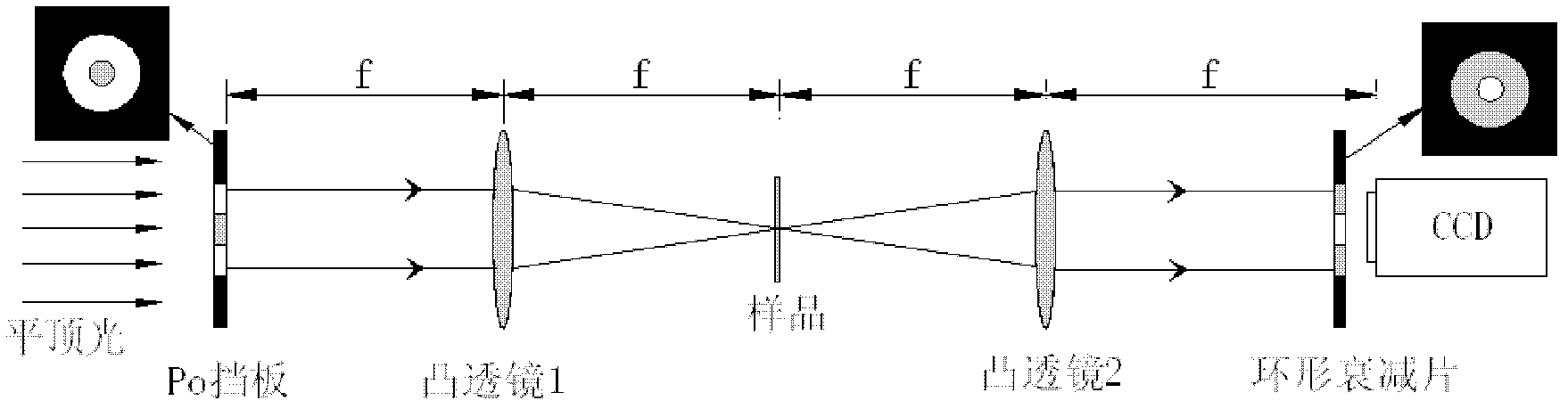
[0023] See attached figure 1 As shown, a high-sensitivity 4f phase imaging method for measuring the optical nonlinearity of materials is composed of a beam splitter, a convex lens, a PO baffle, a ring attenuator, and a CCD detector. The pulsed laser is focused on the sample to be tested.
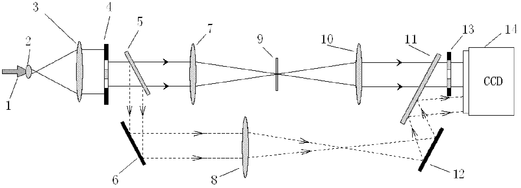
[0024] figure 2 It is a diagram of the experimental setup of the 4f phase imaging method for highly sensitive measurement of optical nonlinearity of materials. The experimental device can be divided into three parts: beam expanding system, measuring system and reference system. The beam expansion system is composed of a beam expander convex lens 2 and a collimating convex lens 3; the measurement system is composed of a PO baffle 4, a convex lens 7, a convex lens 10, an annular attenuator sheet 13, and a CCD detector 14; the reference system is composed of a half mirror 5 , The reflecting mirror 6, the convex lens 8, the reflecting mirror 12, and the half mirror 11. Among them, the sample 9 to be tested is placed on the focal plane of the convex lens 7. The convex lens 7 and the convex lens 10 form a 4f system. The PO baffle 4 and the CCD detector 14 are respectively located on the 4f system object and image plane, and the annular attenuator 13 is close to the CCD receiving surface .
[0025] The pulsed laser emitted from the laser is first expanded by the beam expanding system, and the expanded laser passes through the PO baffle 4, the diameter of the expanded beam spot is larger than the outer diameter of the PO baffle 4 R a It is much larger. The incident light can be regarded as a flat-top light. The beam is split by 5 half mirrors and divided into two paths. The direct light is focused on the sample 9 by the convex lens 7, and the sample is excited to produce nonlinearity, making the incident pulse The laser light intensity and phase change, pass through the convex lens 10 and the annular attenuator 13, and finally image on the CCD target surface. The other beam split by the half mirror 5 passes through the mirror 6, the convex lens 8, the mirror 12, and the half mirror 11 to form an image on the target surface to form a reference spot for monitoring the laser pulse time and space. Unevenness.
[0026] image 3 It is a schematic diagram of the PO baffle in the embodiment; the aperture radius is R a , Where the radius of the center PO part is R i , Compared with the surrounding annular area, its linear transmittance is one percent, and a phase shift of π/2 occurs.
[0027] Figure 4 It is a schematic diagram of the annular attenuator sheet 13 in the embodiment; the central transmittance is 1, and the linear transmittance of the annular region is 1%.
[0028] In this embodiment, a laser with a wavelength of 532nm, a pulse width of 21ps, and a sample thickness of 1mm are selected. The sample to be tested is carbon disulfide (CS 2 ), its nonlinear refractive index n 2 =3.2×10 -18 m 2 /W. The normalized radial intensity distribution of the conventional 4f and the PO baffle 4f are compared.
[0029] For CS 2 The specific process of the theoretical calculation of the nonlinear calculation example is as follows:
[0030] Assuming that the incident beam is fundamental mode Gaussian light, its field strength expression is:
[0031] E ( r , t ) = E 0 exp [ - r 2 ω e 2 ] exp [ - t 2 2 τ 2 ] - - - ( 1 )
[0032] Where E 0 Is the maximum field strength of the pulsed laser, r is the radius of the beam, ω e Is the beam waist radius of the incident beam, and τ is the time of 1/e half width of the pulsed light.
[0033] The transmittance of PO baffle 4 is:
[0034] t ( r ) = 0.01 e i π 2 r R i 1 R i ≤ r ≤ Ra - - - ( 2 )
[0035] Where R i Is the radius of the center PO, R a Is the outer diameter of the transparent area.
[0036] The field strength distribution behind the PO baffle 4 is:
[0037] E 01 (r,t)=E(r,t)t(r) (3) The light field propagating to the surface of the sample can be obtained by the Fourier transform formula, set as E 02 In the sample, considering the approximation of the slow-varying amplitude and the approximation of the thin sample, the amplitude and phase changes of the pulsed laser propagate in the sample to satisfy
[0038] ∂ I ∂ z ′ = - ( α 0 + βI ) I
[0039] dΔφ d z ′ = k n 2 I - - - ( 4 )
[0040] Where n 2 Is the nonlinear refractive index of the sample, α 0 Is the linear absorption rate of the sample, β is the non-linear absorption coefficient of the sample, I=|E 02 | 2 (z'=0 place) is the intensity of light acting on the sample. z'The optical path of the laser in the sample.
[0041] Then the light field on the back surface of the sample is:
[0042] E 03 ( r 1 , t ) = E 02 ( r 1 , t ) e - α 0 L / 2 ( 1 + q ) ( ikn 2 / β - 1 / 2 ) - - - ( 5 )
[0043] The light field propagating from the back surface of sample 9 to the annular attenuator is obtained by the reversible Fourier transform, which is set as E 04. The transmittance function of the annular attenuator 13 can be expressed as:
[0044] t 1 ( r ) = 1 r R i 0.01 R i ≤ r ≤ Ra - - - ( 6 )
[0045] Where R i Is the outer diameter of the central transparent area, R a It is the outer diameter of the annular attenuation part.
[0046] The light intensity on the CCD target surface can be expressed as:
[0047] I(r,t)=|E 04 t 1 (r)| 2 (7) In this embodiment, the incident energy is 0.1 μJ, and the radius of the PO area at the center of the PO baffle is R i =0.6mm, the outer diameter of the annular area R a = 3mm, the focal length of the convex lens 7 and the convex lens 10 is 412mm. Figure 5 In order to use the PO baffle light path to simulate the radial light intensity distribution, Image 6 In order to use conventional PO, the 4f measurement system simulates the radial light intensity distribution, and it can be seen that the contrast between the central nonlinear change and the peripheral linear spot is greatly improved.
[0048] The method of the present invention is different from the original 4f phase coherent imaging system in that the center of the circular aperture is placed on the incident plane to realize the PO function, while the intensity of the incident light in the area is linearly attenuated. In the 4f system receiving plane, The incident surface matches the annular attenuator to attenuate the light intensity outside the center in the same proportion. When the PO diaphragm on the incident surface has a small proportion of the entire diaphragm, the extreme value of the light intensity on the spectrum surface is mainly contributed by the outer ring area of ​​the PO. Part of the transmitted light from the PO can be regarded as straight light, and this part of the light forms a central area in the image plane. Linear spot, that is, background light. Part of the light beam in the ring area is nonlinearly modulated by the material, and part of the light beam enters the central area and interferes with the PO direct light. Its intensity is proportional to the direct light field intensity and the nonlinear phase shift. This part of the light intensity is superimposed on the central linear spot. The gray value of the central area is modulated and becomes signal light. Therefore, the background light is proportional to the PO incident light intensity, and the signal light is proportional to the PO incident photoelectric field intensity, which attenuates the light intensity in this area and has little effect on the nonlinear modulation of the material on the spectrum surface, but it realizes the background light and signal Different proportions of light attenuate, thereby improving the measurement sensitivity of the system.

PUM

no PUM

Description & Claims & Application Information

We can also present the details of the Description, Claims and Application information to help users get a comprehensive understanding of the technical details of the patent, such as background art, summary of invention, brief description of drawings, description of embodiments, and other original content. On the other hand, users can also determine the specific scope of protection of the technology through the list of claims; as well as understand the changes in the life cycle of the technology with the presentation of the patent timeline. Login to view more.

Similar technology patents

High-sensitivity spectrophotometer

PendingCN112414946AIncrease measurement lengthHigh measurement sensitivity
Owner:王家高

Flexible hole expanding device and method

PendingCN111720059ASolve vulnerableGuaranteed reliability
Owner:HENAN POLYTECHNIC UNIV

Bending measurement structure of asymmetric double-core optical fiber, experimental instrument and sensor

PendingCN114562953AHigh measurement sensitivitycompact structure
Owner:BEIJING UNIV OF POSTS & TELECOMM

Method for determining genotoxic impurities in doxofylline bulk drugs

ActiveCN111426760AHigh measurement sensitivityeasy to operate
Owner:陕西省食品药品监督检验研究院

Kit for determining TAT content and preparation method thereof

ActiveCN114689875AHigh measurement sensitivityStrong specificity
Owner:SHENZHEN DYMIND BIOTECH

Capacitive touch induction screen and touch terminal thereof

PendingCN112328128ASolve vulnerableImprove tempered strength
Owner:烟台正海科技股份有限公司

Classification and recommendation of technical efficacy words

  • High measurement sensitivity
  • Solve vulnerable

High-dynamic-range precise scattering feature measuring system

InactiveCN108535218AHigh measurement sensitivityImprove dynamic range
Owner:黄智强

Clamp-type flange leakage monitoring device

InactiveCN106932147AHigh measurement sensitivityavoid disaster
Owner:RES INST OF NUCLEAR POWER OPERATION +1

Simple heat flow detection apparatus

InactiveCN103792026AHigh measurement sensitivitySimple system structure
Owner:XIAN DAOHENG TRANSPORTATION EQUIP TECHCO

Detection equipment of Coriolis mass flow meter

InactiveCN1544891AHigh measurement sensitivitylower requirement
Owner:HUAZHONG UNIV OF SCI & TECH

Flexible hole expanding device and method

PendingCN111720059ASolve vulnerableGuaranteed reliability
Owner:HENAN POLYTECHNIC UNIV

Capacitive touch induction screen and touch terminal thereof

PendingCN112328128ASolve vulnerableImprove tempered strength
Owner:烟台正海科技股份有限公司
Why Eureka
Try Eureka