
Cleaning method of reaction chamber

A reaction chamber and cleaning gas technology, applied in the direction of cleaning methods, cleaning methods and utensils, chemical instruments and methods using gas flow, etc., can solve the problem of pressure control valves not working properly, reaction chamber cleaning is not clean, pipelines Blockage and other problems, to improve the cleaning effect, improve the yield rate of the product, and ensure the effect of normal work

Active Publication Date: 2012-08-01
SEMICON MFG INT (SHANGHAI) CORP
View PDF5 Cites 12 Cited by
  • Summary
  • Abstract
  • Description
  • Claims
  • Application Information

AI Technical Summary

Problems solved by technology

[0007] The present invention solves the problems in the prior art that the reaction chamber is not cleaned cleanly, which leads to the failure of the pressure control valve to work normally and the blockage of part of the pipeline between the reaction chamber and the air pump.

Method used


Image

  • Cleaning method of reaction chamber

Examples


Embodiment 1

[0036] In this embodiment, due to the method of depositing SiO using TEOS and ozone or oxygen 2 as an example, so its by-product is usually SiO 2 , for SiO 2 For cleaning, the cleaning gas generally used is a mixed gas of fluorine-containing gas and oxygen, wherein the fluorine-containing gas is hexafluoroethane (C 2 f 6 ), CF 4 , nitrogen trifluoride (NF 3 )one of a kind. for C 2 f 6 、CF 4 In terms of C 2 f 6 or CF 4 gas, while using radio frequency source or high frequency source to C 2 f 6 or CF 4 Plasma, while for NF 3 In other words, the NF is first passed through the plasma generator 3 Plasma, then NF 3 The plasma is directly passed into the reaction chamber.

[0037] In this example, C 2 f 6 As an example, the purge gas is C 2 f 6 and O 2 The mixed gas is passed into the reaction chamber, and at the same time, the C 2 f 6 and O 2 The mixed gas plasma, described in this example C 2 f 6 The flow rate is 2000 sccm to 3000 sccm, for example: 2000 ...

Embodiment 2

[0047] In this embodiment, SiO is still deposited by using TEOS and ozone or oxygen 2 As an example, the difference is that the pressure control valve in this embodiment is a pressure control valve with a fan blade structure, which controls the pressure of the reaction chamber through the opening angle of the fan blade. For the pressure control valve with fan blade structure, as the thickness of the deposited film layer in the reaction chamber increases, the fan blade will also be covered with a thick layer of by-products (usually SiO 2 ).

[0048] In the present embodiment, the first step of cleaning is similar to that in Example one, C 2 f 6 The flow rate is 2000sccm~3000sccm, O 2 The flow rate is 3000sccm ~ 4500sccm, the first pressure is 2Torr ~ 10Torr, that is, those skilled in the art can according to the C in the cleaning gas 2 f 6 and O 2 The flow range and the range of the first pressure to choose C 2 f 6 and O 2 The flow rate and the first pressure value, ac...


PUM


Abstract

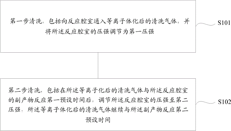
The invention discloses a cleaning method of a reaction chamber. The method is used to clean a by-product of the reaction chamber. The method comprises: a first step of cleaning, which includes feeding a plasma cleaning gas into the reaction chamber and adjusting the pressure of the reaction chamber into a first pressure; a second step of cleaning, which includes adjusting the pressure of the reaction chamber into a second pressure after the plasma cleaning gas reacts with the by-product of the reaction chamber for first preset time and then continuously carrying out the reaction between the plasma cleaning gas with the by-product for second preset time. By using the cleaning method of the reaction chamber, parts of pipelines among a pressure control valve, the reaction cavity and a suction pump can be cleaned so that normal working of the pressure control valve can be guaranteed and a yield rate of a product can be increased.

Description

technical field [0001] The invention relates to the technical field of semiconductors, in particular to a method for cleaning a reaction chamber. Background technique [0002] Chemical vapor deposition (CVD) is a process of depositing a solid film on the surface of a silicon wafer through a chemical reaction of gas mixing. Generally speaking, CVD includes atmospheric pressure chemical vapor deposition (APCVD), low pressure chemical vapor deposition (LPCVD), plasma enhanced chemical vapor deposition (PECVD), and high density plasma chemical vapor deposition (HDPCVD). [0003] Silicon dioxide (SiO2) is usually deposited by CVD 2 ), SiO can be deposited by TEOS process 2 , that is, tetraethyl orthosilicate (TEOS) is used, and the molecular formula is Si(C 2 h 5 o 4 ), and ozone (O 3 ) or oxygen to reactively deposit SiO 2 , using TEOS and ozone or oxygen to deposit SiO 2 When the deposition rate is relatively fast, the chip output per hour (WPH) of the machine is greatl...

Claims


Application Information

Patent Timeline
IPC IPC(8): H01L21/00B08B5/00
Inventor 许亮
Owner SEMICON MFG INT (SHANGHAI) CORP
Learn More