
Fluidized bed plasma garbage-gasifying equipment and gasifying process thereof

A technology of fluidized bed gasification and fluidized bed gasifier, which is applied in granular/powder fuel gasification, petroleum industry, manufacture of combustible gas, etc. and other problems, to achieve the effect of improving gasification efficiency and throughput, improving gasification efficiency and reducing adhesion

Inactive Publication Date: 2012-08-08
大连鑫宝生物质能有限公司
View PDF5 Cites 19 Cited by
  • Summary
  • Abstract
  • Description
  • Claims
  • Application Information

AI Technical Summary

Problems solved by technology

[0006] First of all, direct gasification of garbage with a plasma torch requires a huge amount of power, and its power consumption rate can reach 30% to 45% of its power production capacity. Due to the high power consumption, the operating cost is greatly increased, making it unsuitable for commercial operation. the value of
[0007] Second, the existing plasma torch gasification garbage technology cannot solve the problem of dioxins well. If only the plasma torch is used in conjunction with the subsequent adsorption tower and bag filter, the dioxin content cannot be truly reduced. lower than national standard
[0008] Third, using a plasma torch to directly gasify garbage, due to the uneven distribution of its temperature field, the garbage cannot be completely treated at high temperature, and there will be a large amount of dioxins and other harmful substances in the discharged waste residue, which makes the treatment of its waste residue become a problem. a problem
[0009] On the other hand, most of the existing gasifiers use fixed beds, the gasification efficiency is low, usually only 50-60%, and the throughput is small, usually only 0.5T / h, the maximum not exceeding 3.6T / h

Method used


Image

  • Fluidized bed plasma garbage-gasifying equipment and gasifying process thereof
  • Fluidized bed plasma garbage-gasifying equipment and gasifying process thereof
  • Fluidized bed plasma garbage-gasifying equipment and gasifying process thereof

Examples


Embodiment Construction

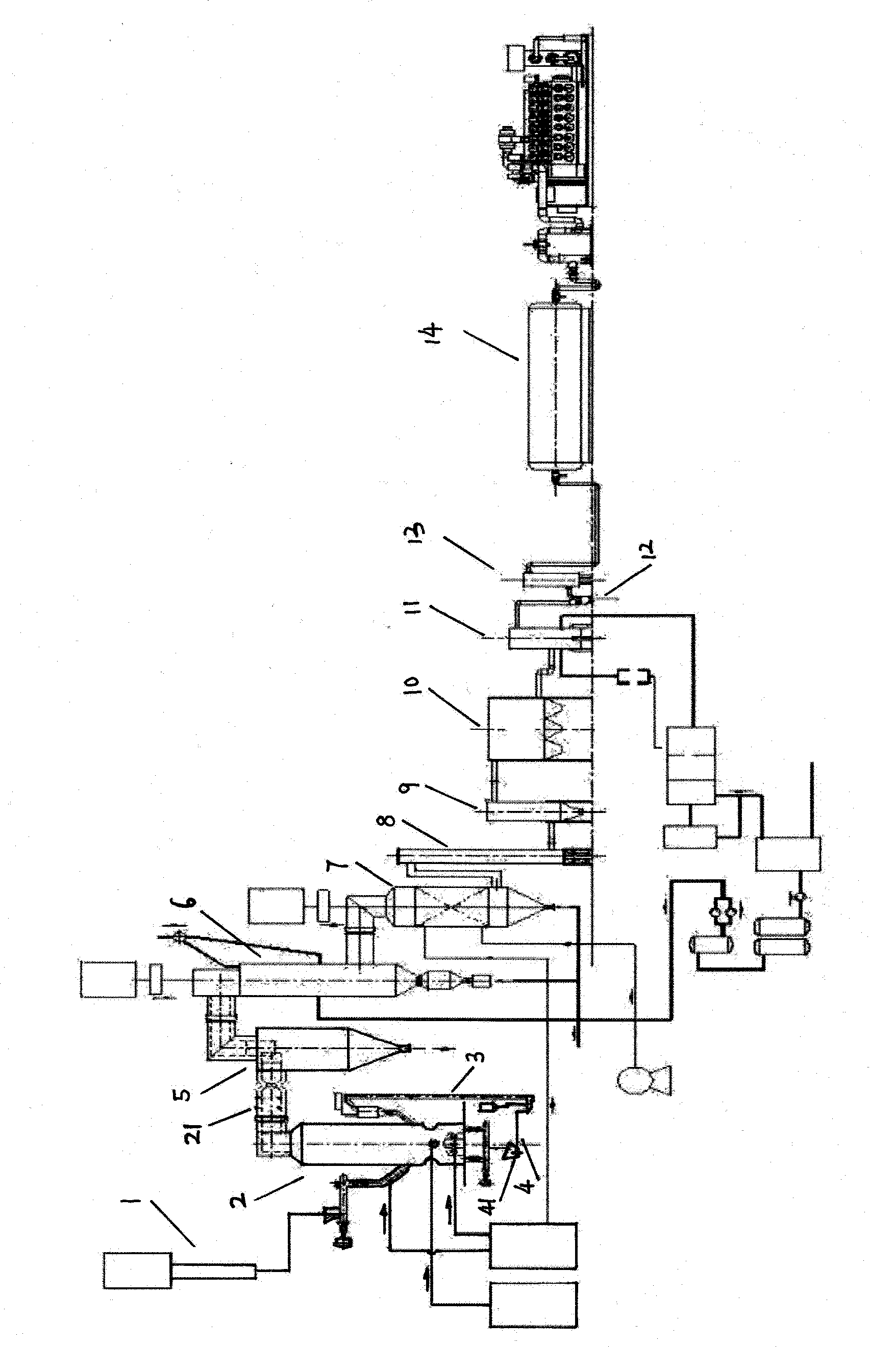
[0053] A fluidized bed gasification garbage equipment, including a feeding system 1, a plasma gasification fluidized bed 2, a feeding system 3, a slag discharge system 4, a cyclone separator 5, a rapid cooling waste heat boiler 6, a rapid cooling tower 7, a cooling tower 8, adsorption tower 9, bag type dust removal device 10, sulfur removal device 11, water ring compressor 12, steam-water separator 13, gas storage and distribution cylinder 14, and equipment control system, such as figure 1 shown;

[0054] The feeding system 1 is composed of a double auger feeder. The two augers are placed side by side and can move laterally. When the auger jams the material, it can be separated automatically so that the jammed material continues to move forward.

[0055] The plasma gasification fluidized bed 2 includes a furnace wall, an air distribution plate, and a plasma torch 21;

[0056] The furnace wall is composed of a three-layer structure, the innermost layer is made of corundum cast...


PUM


Abstract

The invention relates to fluidized bed plasma garbage-gasifying equipment and a gasifying process thereof. A gasifying furnace of the gasifying equipment is a plasma gasifying fluidized bed. The gasifying equipment comprises a fluidized bed gasifying furnace, wherein a plasma torque is arranged at a smoke outlet at the top of the fluidized bed; the inner layer of the wall of the fluidized bed gasifying furnace is a corundum cast material layer; an ash plasma processing cabin is arranged on the tail part of a slag discharging system; and the inner layer of the fluidized bed gasifying furnace is a corundum cast material layer. The gasifying process comprises the following steps of: (a) generating mixed gas; (b) discharging slag and returning the materials; and (c) purifying and filtering gas. In the process, the mixed gas generated in the fluidized bed furnace is re-heated to more than 1,000 DEG C through plasma to perform tar recombination and eliminate dioxin on the surface of a part of ash, and the mixed gas is cooled from 800 DEG C to 180 DEG C within 0.6 second under the action of quenching, so a re-polymerization interval of the dioxin is completely avoided. The fluidized bed plasma garbage-gasifying equipment has the characteristics of harmlessness, environment friendliness, energy conservation and consumption reduction.

Description

technical field [0001] The invention relates to the plasma gasification power generation technology of domestic garbage, in particular to a plasma garbage gasification equipment and a gasification process thereof. Background technique [0002] The domestic waste disposal methods in my country are mainly landfill and incineration. Landfill not only occupies a large amount of land, but also pollutes groundwater, which is a last resort. Nevertheless, there are not many sites available for landfill in areas where land resources are scarce. Although the incineration method has a high volume reduction ratio and can recover energy, it is strongly opposed by the public due to pollution problems such as dioxins: domestic waste and other wastes are prone to produce dioxins when the combustion temperature is lower than 300-550 ° C; During the incineration of chlorine-containing plastics, the incineration temperature is lower than 800°C, and dioxins are easily generated. Dioxins are e...

Claims


Application Information

Patent Timeline
IPC IPC(8): C10J3/56C10J3/84
Inventor 张建超张瑜杨开域姜晨旭余传林何成国
Owner 大连鑫宝生物质能有限公司
Learn More