Optical fiber and manufacturing method thereof

A technology of optical fiber preform and optical fiber, which is applied in the direction of cladding optical fiber, manufacturing tools, glass manufacturing equipment, etc., can solve the problems affecting the reduction of optical fiber transmission loss, the difficulty of realizing low-attenuation optical fiber, affecting the strength and service life of optical fiber, etc., to achieve Effect of Transmission Loss Reduction

Active Publication Date: 2012-09-05
YANGTZE OPTICAL FIBRE & CABLE CO LTD
View PDF3 Cites 24 Cited by
  • Summary
  • Abstract
  • Description
  • Claims
  • Application Information

AI Technical Summary

Problems solved by technology

[0006] At the same time, due to the high-temperature viscosity mismatch of the fiber material components, the fiber structure is incomplete, which seriously affects the reduction of fiber transmission loss, and it is difficult to achieve low-attenuation fiber manufacturing; on the other hand, the high-temperature viscosity mismatch is due to the core-clad material With different characteristic temperatures such as glass softening temperature and transformation temperature, during the drawing process, different specific temperatures of the core will cause a large residual stress in the optical fiber
This not only destroys the designed waveguide structure, but also affects the strength and service life of the optical fiber

Method used


Image

  • Optical fiber and manufacturing method thereof
  • Optical fiber and manufacturing method thereof
  • Optical fiber and manufacturing method thereof

Examples


Embodiment 1

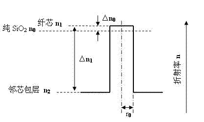
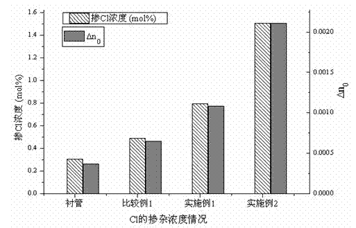
[0033] Example 1 , the optical fiber material is prepared by the in-tube method, the concentration difference △[F] between the cladding and core materials is 1.9 mol%, and the difference △[OH] between the core and cladding materials is 1×10 -6 mol%, the concentration difference △[Cl] between the fiber core and the cladding material is 1.52 mol%, and the fiber core material is not doped with alkali metal. image 3 It is the change of the refractive index caused by the doping of different concentrations of Cl, and the different doping concentrations of Cl are adjusted by changing the proportion of the reaction gas and the moving speed of the reaction zone. Figure 4 is the Cl concentration (mol%) contained in the single-mode optical fiber in the comparative example.

Embodiment 2

[0034] Example 2 , the optical fiber material is prepared by the in-tube method. The concentration difference △[F] between the cladding and core materials is 2.33 mol%, the difference △[OH] between the core and cladding materials is 0.01 ppm_mol. The concentration difference △[Cl] of the cladding material doped with chlorine is 1.53 mol%, and the fiber core material is not doped with alkali metal.

Embodiment 3

[0035] Example 3 , the optical fiber material is prepared by the in-tube method, the concentration difference △[F] between the cladding and core materials is 3.5 mol%, the difference △[OH] of the hydroxyl concentration between the core and cladding materials is 0.01 ppm_mol, and the core and cladding materials are 0.01 ppm_mol. The concentration difference △[Cl] of the cladding material doped with chlorine is 2.84 mol%, and the fiber core material is not doped with alkali metal.


PUM

PropertyMeasurementUnit
scattering coefficientaaaaaaaaaa

Abstract

The invention relates to an optical fiber and a manufacturing method of optical fiber. The optical fiber comprises a core layer and a coating layer, the optical fiber is characterized in that the average refractive index n1 of the core layer, the refractive index n2 of the coating layer and the refractive index n0 of pure silicon dioxide meet the following formula: n1 is equal to (0.997-1.0012)*n0, and n2 is equal to n1-(0.0025-0.0045)*n0; the core layer is a core layer doped with alkali metal ions or a core layer doped with no alkali metal ions, and the coating layer is composed of a silicon dioxide base material doped with fluorine and chlorine and containing a hydroxyl radical; and the fluorine doping concentration difference delta [F] of the materials of the coating layer and the core layer, the hydroxyl radical concentration difference delta [OH] of the materials of the core layer and the coating layer, the fluorine doping concentration difference delta [Cl] of the materials of the core layer and the coating layer and the alkali metal ion doping concentration sum [M] of the material of the core layer meet the following formulation: delta [F]-delta [Cl]-300*[M]-150000* delta [OH] <=0.8 mol%. According to the invention, the doping ingredients and the concentration difference are controlled to match the high temperature viscosity of the materials of the core layer and the coating layer of the optical fiber so as to obtain a single mode optical fiber with reduced Rayleigh scattering attenuation, and the scattering coefficient of the optical fiber is reduced to be not larger than 0.85 so as to effectively reduce the transmission dissipation of the optical fiber.

Description

technical field [0001] The invention relates to an optical fiber and a manufacturing method thereof. The optical fiber material has high-temperature viscosity matching of core layer and cladding material and low attenuation characteristics of reduced scattering loss, and belongs to the technical field of communication optical fiber manufacturing. Background technique [0002] Optical fiber communication technology that uses light waves as the carrier of information transmission and optical fiber as the information transmission medium, because the information transmission frequency band is relatively wide, the communication rate is high, the capacity is large, and the loss is low, the volume is small, the weight is light, and it is resistant to electromagnetic interference and is not easy. A series of advantages such as crosstalk, so it is favored by the communication field, and its development is extremely rapid. Optical fiber communication technology has become a very impor...

Claims


Application Information

Patent Timeline
Patent Type & Authority Applications(China)
IPC IPC(8): G02B6/02C03B37/018C03B37/025
CPCC03B37/01413C03B37/01807C03B2201/12C03B2201/20C03B2201/50C03B2203/22
Inventor 熊良明杨晨罗杰童维军李江王聍曹蓓蓓
Owner YANGTZE OPTICAL FIBRE & CABLE CO LTD
Why Eureka
Try Eureka