
Water treatment process for recovering heavy oil recovery produced water to serve as boiler feed water

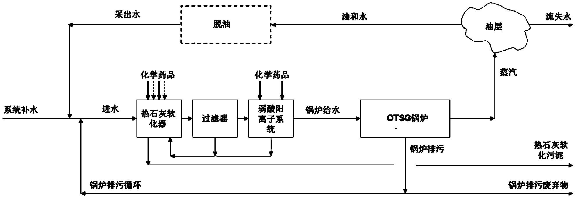
A boiler feed water and produced water technology, applied in water/sewage treatment, heating water/sewage treatment, water/sludge/sewage treatment, etc., can solve problems such as high production cost, high boiler sewage discharge, and affecting the operation of the evaporation system

Active Publication Date: 2014-07-02
江苏中圣清洁能源有限公司
View PDF5 Cites 0 Cited by
  • Summary
  • Abstract
  • Description
  • Claims
  • Application Information

AI Technical Summary

Problems solved by technology

Regardless of the process used, the difficulty to be overcome in the produced water evaporation process is that silicon components and hard components are easy to scale, which affects the operation of the evaporation system
In addition, due to the presence of volatile components, such as organic matter and carbonate, more production costs are required for evaporation to produce distilled water, because additional water treatment facilities need to be set up, the chemical composition of boiler feed water is higher, and the boiler blowdown is higher

Method used


Image

  • Water treatment process for recovering heavy oil recovery produced water to serve as boiler feed water
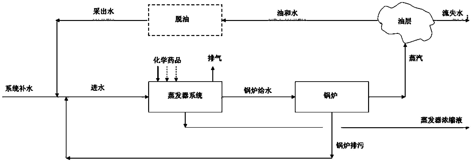
  • Water treatment process for recovering heavy oil recovery produced water to serve as boiler feed water
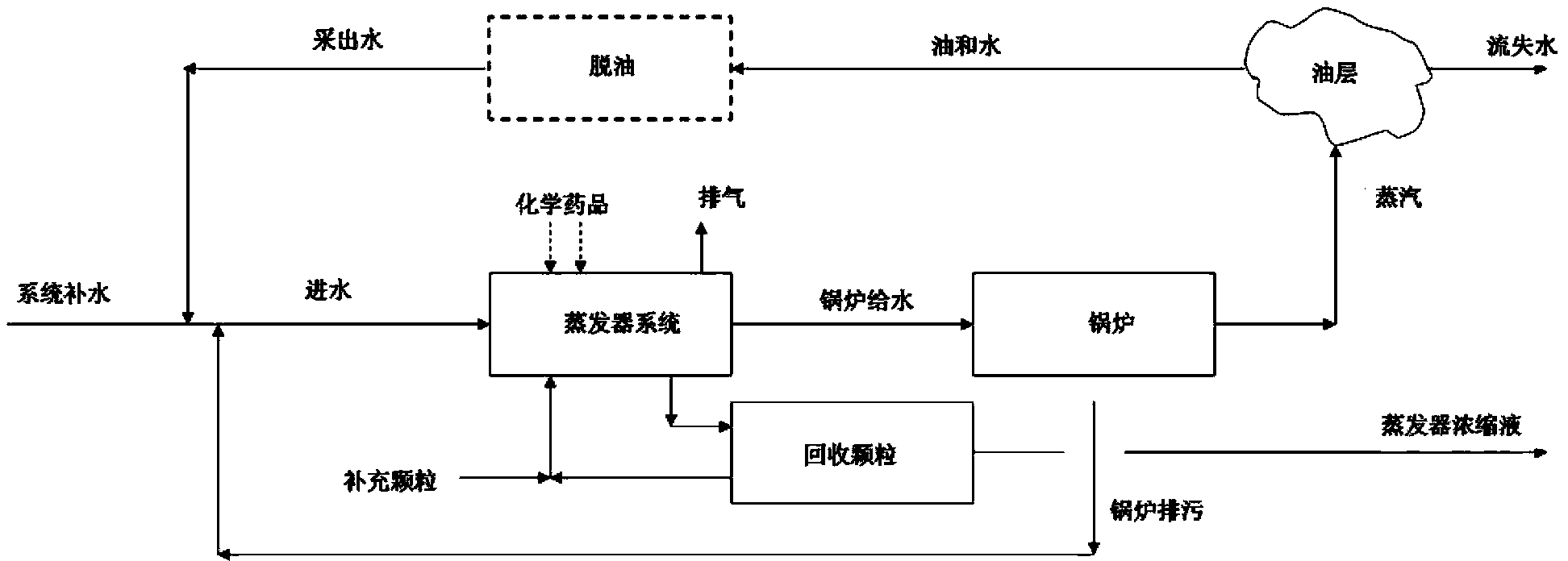
  • Water treatment process for recovering heavy oil recovery produced water to serve as boiler feed water

Examples


Embodiment 1

[0116] a kind of like Image 6 The liquid distributor 10 for the vertical falling film evaporator shown is mainly composed of a guide body 9 with a concave surface around the main body 6 and a bottom area of ​​the top cover 1 larger than the area of ​​the heat exchange tube 8 of the vertical falling film evaporator, and the The diversion body 9 is movably supported at the corresponding position in the upper part of the heat exchange tube 8 of the vertical falling film evaporator, so that the edge of the bottom surface of the top cover 1 of the diversion body 9 and the upper surface of the upper tube sheet 7 of the vertical falling film evaporator are separated by a certain gap to form a gap. The support part 5 of the liquid channel is composed. The guide body 9 is symmetrically distributed along the central axis of the heat exchange tube of the vertical falling film evaporator, and consists of a main body 6 and a top cover 1 . The top cover 1 is in the shape of a hat, and its...

Embodiment 2

[0120] a kind of like Figure 9 The liquid distributor 10 for the vertical falling film evaporator shown is mainly composed of a guide body 9 with a concave surface around the main body 6 and a bottom area of ​​the top cover 1 larger than the area of ​​the heat exchange tube 8 of the vertical falling film evaporator, and the The diversion body 9 is movably supported on the corresponding upper part of the heat exchange tube 8 of the vertical falling film evaporator, so that the edge of the bottom surface of the top cover 1 of the diversion body 9 and the top surface of the upper tube plate 7 of the vertical falling film evaporator are separated by a certain gap to form The support part 5 of the liquid inlet channel is composed. The guide body 9 is symmetrically distributed along the central axis of the heat exchange tube of the vertical falling film evaporator, and the diameter of the bottom surface of the guide body 9 is 0.6 times the inner diameter of the heat exchange tube 8...

Embodiment 3

[0124] A water treatment system for recovering heavy oil production water as boiler feed water, including a water inflow pretreatment system, an evaporation system, a supplementary particle system, and a particle recovery system.

[0125] The water pre-treatment system includes the water pre-treatment system, including a chemical treatment device, a water preheater and a degasser. The chemical treatment device is composed of dosing equipment 11-1, 11-2, a water inlet tank mixer 12, and a water inlet tank 13. The water inlet tank and the water inlet preheater are connected by a water inlet pump 14 . The incoming water mainly produced water enters the water inlet tank, and the chemical treatment agent is added to the water inlet tank 13 through the dosing equipment 11 - 1 and 11 - 2 , and reacts under the stirring of the water inlet tank mixer 12 . The chemically treated water is pumped into the water preheater 15 by the water pump 14 for preheating, and then enters the degasse...


PUM

PropertyMeasurementUnit
particle sizeaaaaaaaaaa
densityaaaaaaaaaa

Abstract

Disclosed is a water treatment process for recycling produced water from heavy oil recovery to serve as boiler feed water. Inlet water containing produced water as the main component is conveyed to a vertical falling-film evaporator equipped with a brine distribution device, so as to produce distilled water as boiler feed water through evaporation. Scrubbing particles are added to the inlet water containing the produced water as the main component or to circulating strong brine of the vertical falling-film evaporator to form slurry. When the slurry is evaporated by the vertical falling-film evaporator, scaling on the heat exchange surface of the evaporator is prevented or reduced by utilizing the solid particles in the slurry. According to the process, most of produced water is processed into high-quality distilled water used for a boiler to produce steam so as to increase the heavy oil recovery rate, and the process can be directly used for treating the produced water, with a recycling rate higher than 95%, to produce the high-quality boiler feed water used for producing the steam required by heavy oil recovery. The process can also be used for treating boiler blow-off, thereby reducing the emission of a factory, lowering the requirements of physicochemical treatment, and increasing the overall water recycling rate of a water treatment plant.

Description

technical field [0001] The invention belongs to the field of water treatment and relates to a water treatment process for recovering heavy oil production water as boiler feed water. Background technique [0002] Heavy oil recovery involves injecting steam into oil-bearing formations and recovering oil-water mixtures from oil wells. The oil is separated from the water, and the separated water is produced water. In order to recycle the produced water to produce steam, the produced water must be treated to meet the requirements of the steam generator or boiler for steam production. [0003] Steam injection into heavy oil reservoirs is a widely used method for enhanced oil recovery. Typically several tons of steam are required to produce 1 ton of heavy oil, and the steam / oil ratio is often referred to as the oil recovery ratio (SOR). Because the SOR value is generally between 2 and 4, and the water consumption is high, environmental protection and economical aspects encourage...

Claims


Application Information

Patent Timeline
Patent Type & Authority Patents(China)
IPC IPC(8): C02F1/08
CPCC02F1/08B01D1/065C02F1/042
Inventor D.J.彼得森D.K.卡尼纳伽马明刘丰李东
Owner 江苏中圣清洁能源有限公司
Learn More