Porous carbon materials and manufacturing method thereof
A production method and porous carbon technology, applied in the field of porous materials, can solve the problems of high energy and long manufacturing time, and achieve the effects of low energy, increased surface area, and increased charge storage capacity
- Summary
- Abstract
- Description
- Claims
- Application Information
AI Technical Summary
Problems solved by technology
Method used
Image
Examples
no. 1 example
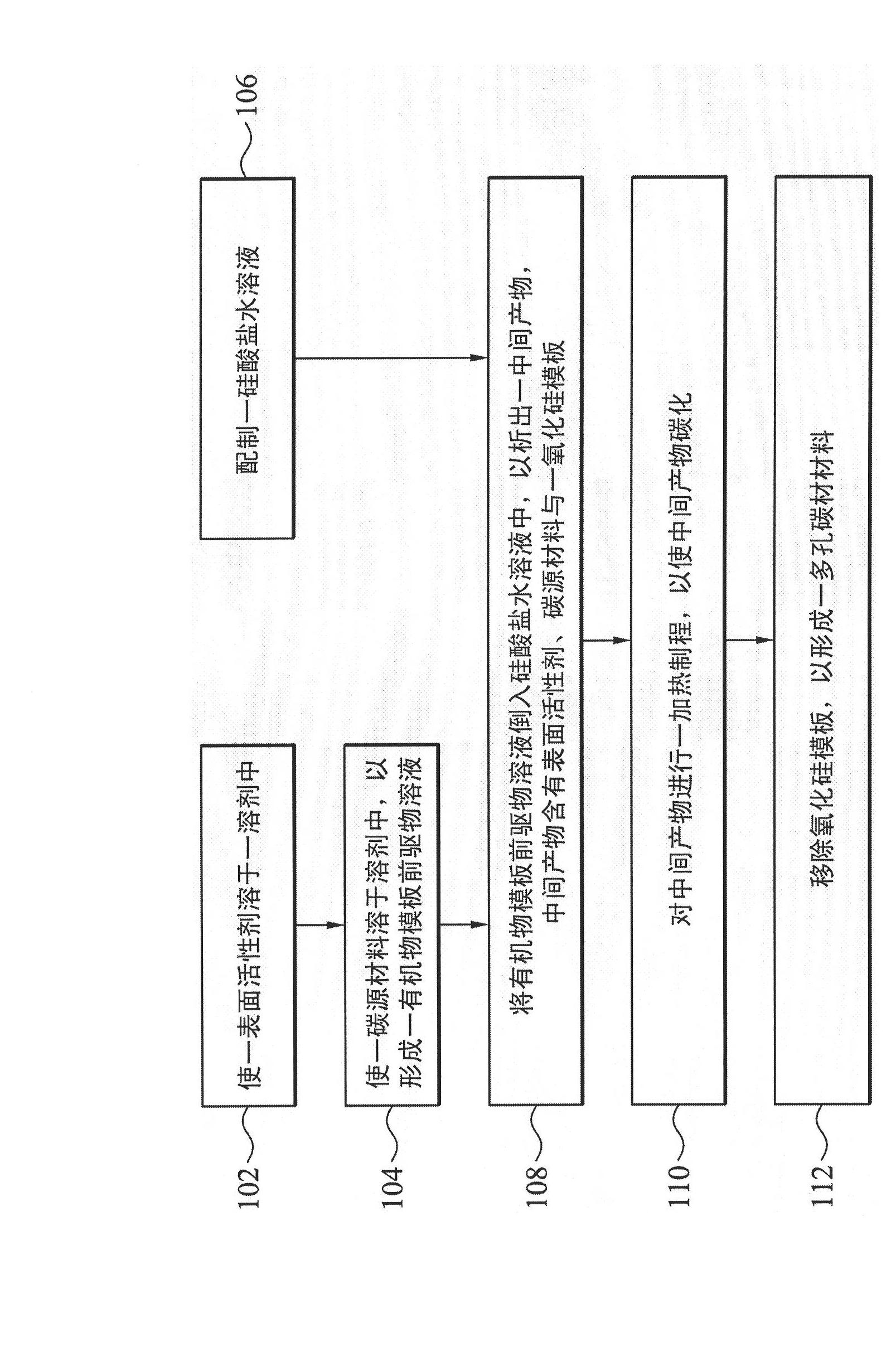
[0041] First, 2 g of surfactant-ethylene oxide propylene oxide triblock copolymer (Pluronic F127) is dissolved in a solvent composed of water and ethanol (the volume ratio of water and ethanol is 0.5, and the total weight is 50 g) , and stirred for several minutes, at this time, the solvent containing the surfactant was in the state of a clear liquid.
[0042] Next, the carbon source material-phenolic resin (0.5-4g) is dissolved in a solvent to form an organic template precursor solution. At this point, the solvent can be placed in a constant temperature bath to balance the carbon source material and the solvent to a set temperature (30° C.), and stirred at the set temperature for 4 hours to form an organic template precursor solution.
[0043] In addition, silicate-sodium silicate (8 g) was placed in water (150 g) and stirred to dissolve in water to form an aqueous silicate solution, after which the aqueous silicate solution was adjusted to a pre-reaction pH value (pH=4), an...
no. 2 example
[0049] The operating steps of the second embodiment are the same as the first embodiment, but wherein the reaction control conditions are adjusted as follows:
[0050] 1. The pH value of the pre-reaction of the silicate aqueous solution is about 4;
[0051] 2. The set temperature (of carbon source material, solvent and silicate aqueous solution) is 40°C;
[0052] 3. The solvent includes water and ethanol, and the volume ratio of water and ethanol is 1.
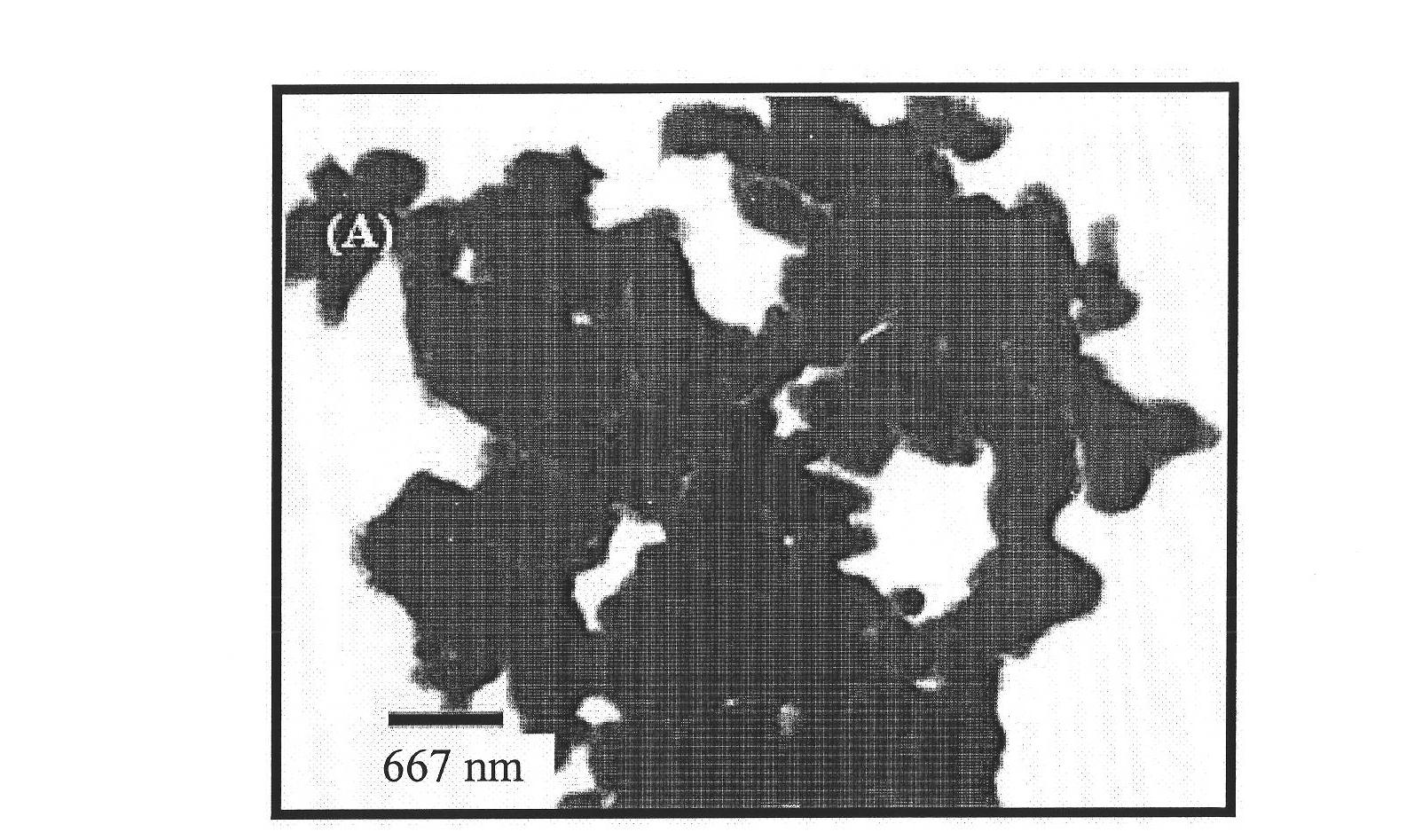
[0053] image 3 It is a transmission electron microscope image of the porous carbon material prepared in the second embodiment.
no. 3 example
[0055] The operating steps of the third embodiment are the same as those of the first embodiment, but wherein the reaction control conditions are adjusted as follows:
[0056] 1. The pH value of the pre-reaction of the silicate aqueous solution is about 4;
[0057] 2. The set temperature (of carbon source material, solvent and silicate aqueous solution) is 40°C;
[0058] 3. The solvent includes water and ethanol, and the volume ratio of water and ethanol is 5.
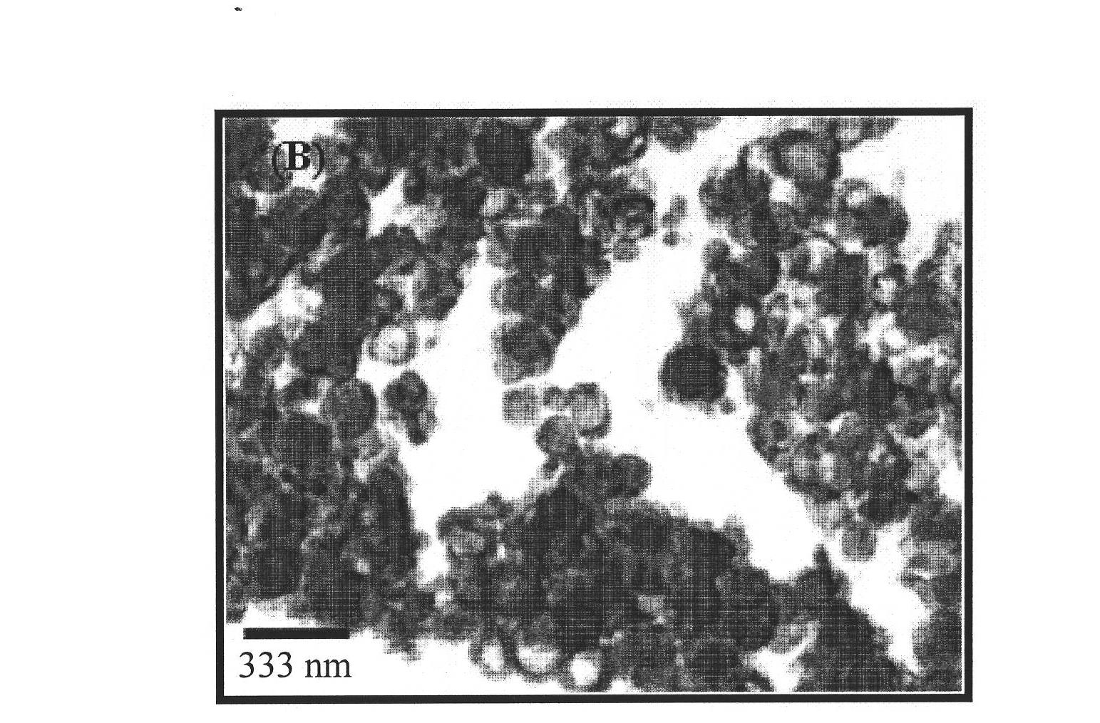
[0059] Figure 4 It is a transmission electron microscope image of the porous carbon material prepared in the third embodiment.
[0060] Please refer to Figure 2 to Figure 4 ,Depend on Figure 2 to Figure 4 It can be seen that as the ratio of ethanol in the solvent increases, the generated porous carbon material has more regular arrangement (well-order) spherical structures ( figure 2 , image 3 ). When the proportion of water is too high (the third embodiment), there will be a change in form, and the reductio...
PUM
 Abstract
Description
Claims
Application Information
 - R&D
- Intellectual Property
- Life Sciences
- Materials
- Tech Scout
- Unparalleled Data Quality
- Higher Quality Content
- 60% Fewer Hallucinations
Browse by: Latest US Patents, China's latest patents, Technical Efficacy Thesaurus, Application Domain, Technology Topic, Popular Technical Reports.
© 2025 PatSnap. All rights reserved.Legal|Privacy policy|Modern Slavery Act Transparency Statement|Sitemap|About US| Contact US: help@patsnap.com


