Eutectic soldering equipment of LED wafer

A eutectic welding and wafer technology, applied in the field of LED chip eutectic welding equipment, can solve the problems of slow heating speed, low maximum temperature, affecting heating effect, etc., achieve good thermal conductivity, improve eutectic accuracy, and speed up heating. Effect

Inactive Publication Date: 2012-09-26
HUIZHOU DAYAWAY EVER BRIGHT ELECTRONICS IND CO LTD
View PDF5 Cites 20 Cited by
  • Summary
  • Abstract
  • Description
  • Claims
  • Application Information

AI Technical Summary

Problems solved by technology

[0004] However, since the eutectic melting point of the LED chip is above 300°C, and the eutectic welding equipment of the LED chip in the prior art generally uses a hot air reflow furnace as a heating device, The heating speed of this heating device is slow, and the maximum temperature that can be reached by heating is relatively low.
In addition, there is also a scheme using infrared w

Method used


Image

  • Eutectic soldering equipment of LED wafer
  • Eutectic soldering equipment of LED wafer
  • Eutectic soldering equipment of LED wafer

Examples


Example Embodiment

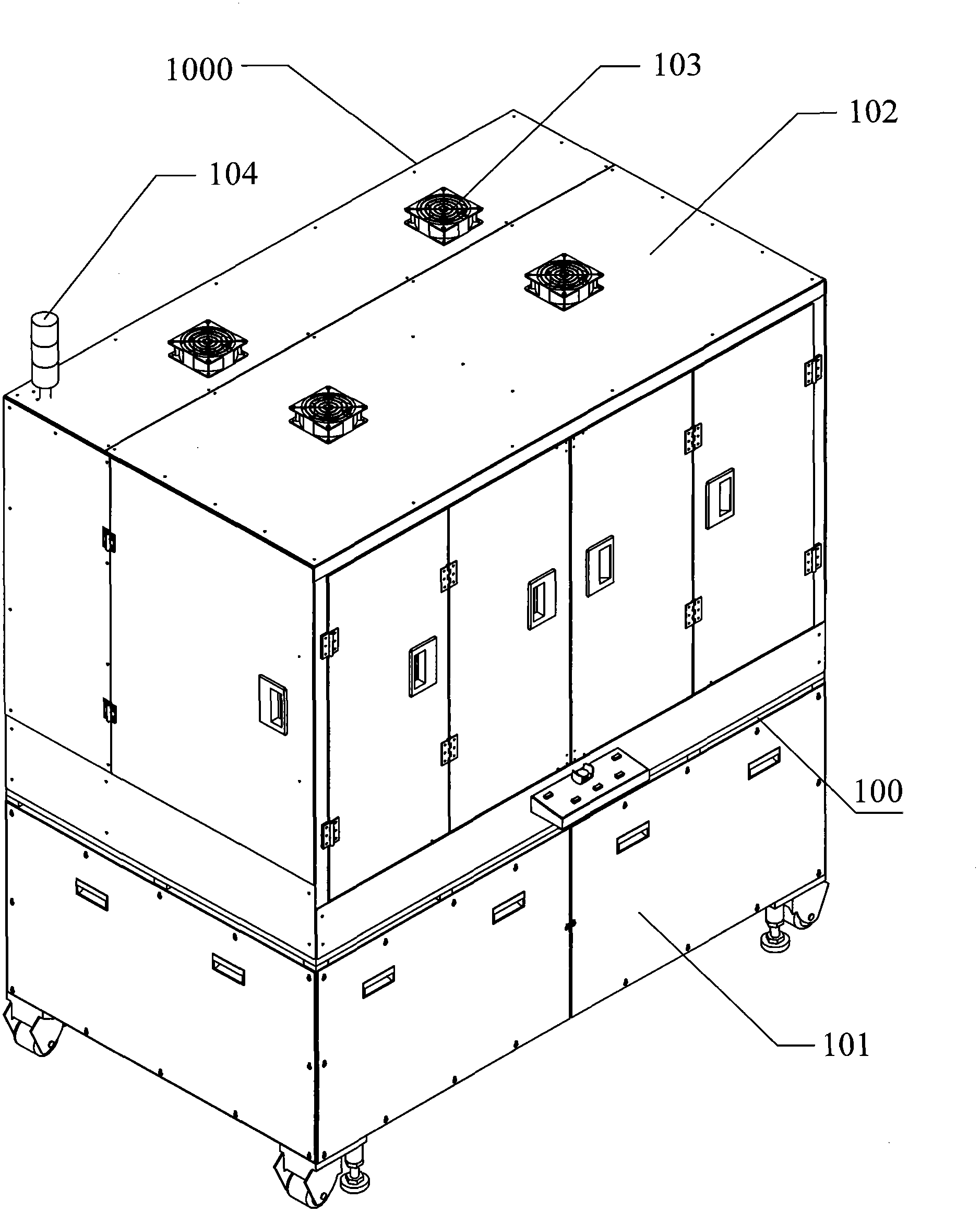
[0055] Reference below Figure 1-Figure 7 Describe in detail an embodiment of the LED chip eutectic welding equipment of the present invention; figure 1 As shown, this embodiment mainly includes a fuselage 1000. The fuselage 1000 mainly includes a bottom box 101 and an upper box 102. The bottom box 102 is provided with a power configuration box (not shown in the figure) and a bottom box. A welding workbench 100 is provided on 102, and a cooling fan 103 and a warning light 104 are provided on the top plate of the upper box 102.

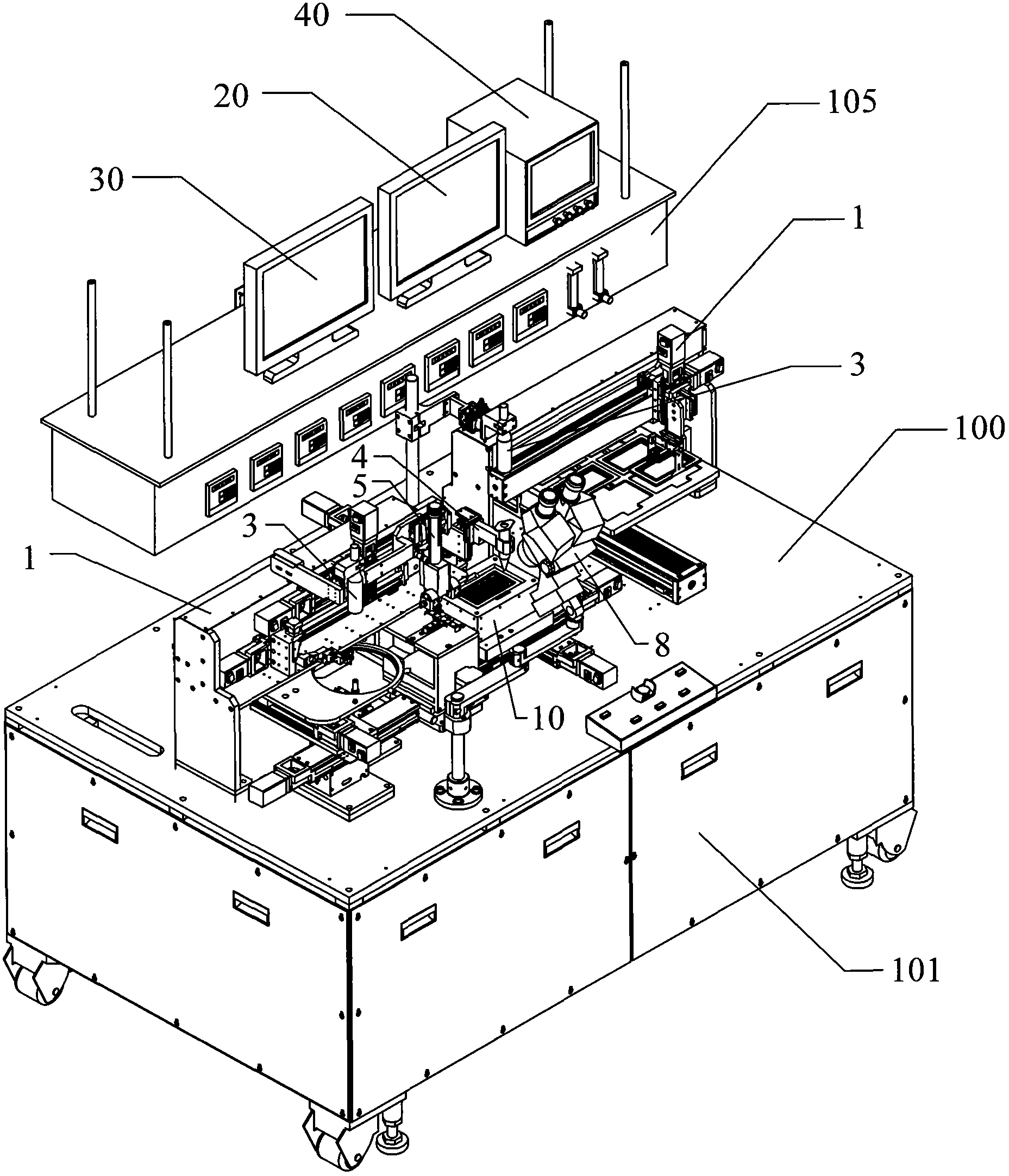
[0056] Also, please refer to figure 2 , The upper box 102 is provided with:

[0057] Drive control system (not shown in the figure), mainly including servo drive system and single-chip control system;

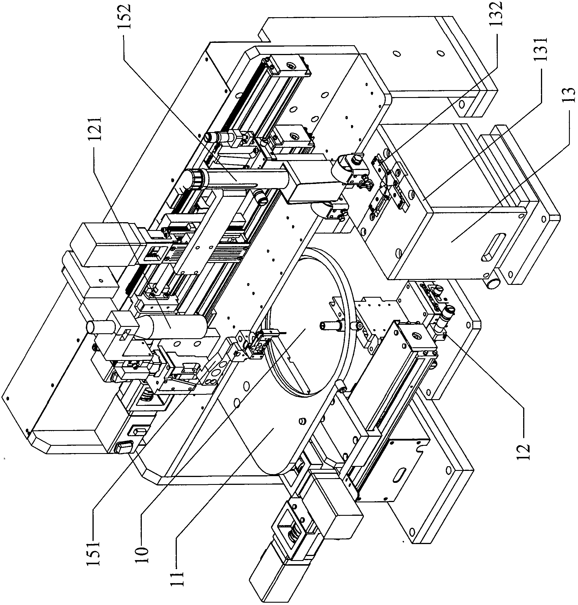
[0058] The eutectic welding platform 10 set in the middle of the front of the welding workbench 100 for placing the chip to be welded and the bracket;

[0059] They are respectively arranged around the sides and the rear of the eutectic welding platform 10, a...


PUM


Abstract

The invention discloses eutectic soldering equipment of an LED wafer. The eutectic soldering equipment comprises a heating device, a drive control system, a power configuration box body, a soldering working table, an eutectic soldering platform arranged in the middle of the front part of the soldering working table, a bracket supplying device and a wafer supplying device which are arranged in a manner of surrounding both sides and the rear part of the eutectic soldering platform respectively, a scaling powder supplying device arranged above the eutectic soldering platform, a nitrogen cooling device arranged on the eutectic soldering platform, a pulse current heating device arranged on one side of the eutectic soldering platform and a constant-temperature current heating device arranged inside the eutectic soldering platform. The eutectic soldering equipment has a high heating speed and high soldering precision, and enables the LED wafer after being soldered to have a better heat transfer effect.

Description

Technical field [0001] The invention relates to LED chip manufacturing technology, in particular to an LED chip eutectic welding equipment. Background technique [0002] Eutectic welding technology has a wide range of applications in the electronic packaging industry, such as the bonding of wafers and substrates, the bonding of substrates and packages, and package caps. Compared with traditional epoxy conductive adhesive bonding, eutectic welding has the advantages of high thermal conductivity, low thermal resistance, fast heat transfer, strong reliability, and high strength after bonding. It is suitable for high-frequency and high-power devices. The interconnection between the chip and the substrate, the substrate and the package. [0003] With the rapid development of LED technology, LED chips and packaging are becoming more and more high-power and integrated. The traditional silver glue bonding process has been difficult to meet the welding process requirements of LED chips. Th...

Claims


Application Information

Patent Timeline
IPC IPC(8): B23K3/00B23K3/047B23K3/08
Inventor 代克明胡华武
Owner HUIZHOU DAYAWAY EVER BRIGHT ELECTRONICS IND CO LTD
Why Eureka
Try Eureka