Milling and grinding tool capable of realizing high-efficient machining of inorganic composite material

An inorganic composite material, milling and grinding technology, applied in the field of milling and grinding tools, can solve the problems of edge chipping of workpieces, difficulty in mass production, tool chipping and other problems

Inactive Publication Date: 2012-10-10
HARBIN INST OF TECH
View PDF4 Cites 9 Cited by
  • Summary
  • Abstract
  • Description
  • Claims
  • Application Information

AI Technical Summary

Problems solved by technology

[0005] (2) The cutting quality of metal matrix and ceramic matrix composite materials is not easy to guarantee
[0006] (3) Although a variety of processing methods for inorganic composite materials have been researched and developed by some research institutions at home and abroad (such as PCD diamond tool cutting technology, ultrasonic vibration cutting technology, electrical processing technology, grinding technology, laser processing technology, etc. ), but these technologies have different degrees of limitations, including tool life issues, processing quality assurance issues, and complex curved surface processing issues. Engineered mass production
[0007] (4) The above-mentioned metal matrix/ceramic matrix composite materials are new materials developed in recent years. It is difficult to find process data for engineering application in the current literature, materials, and m

Method used


Image

  • Milling and grinding tool capable of realizing high-efficient machining of inorganic composite material
  • Milling and grinding tool capable of realizing high-efficient machining of inorganic composite material
  • Milling and grinding tool capable of realizing high-efficient machining of inorganic composite material

Examples


Embodiment Construction

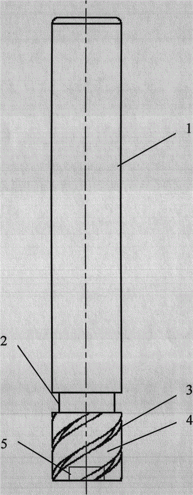
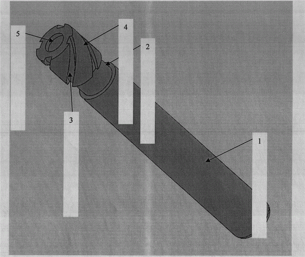
[0030] The base part of the milling tool involved in the present invention is made of No. 45 steel, and it is subjected to quenching and tempering treatment to improve the strength. The size and quality requirements of the handle can refer to milling cutters of the same specification. The structure of the milling tool mainly includes the handle 1. Relief slot 2, chip flute 3, electroplating and cutting part 4, chip space 5, the diameter of the milling tool handle is 10mm, the length is 55mm, and the surface roughness is less than or equal to 0.16μm. The total length of the tool is 70mm, and the width of the cutting part of the grinding tool is 10mm. figure 2 Middle 3 is the four spiral grooves with a certain helix angle evenly distributed on the milling tool for chip removal; figure 2 Middle 5 is the chip space for the milling tool, with a diameter of 5mm and a depth of 2mm; figure 2 5 in the milling tool is a chip pocket with a diameter of 5mm and a depth of 2mm for chip ...


PUM

PropertyMeasurementUnit
Diameteraaaaaaaaaa
Lengthaaaaaaaaaa
Surface roughnessaaaaaaaaaa

Abstract

The invention relates to a milling and grinding tool capable of realizing high-efficient machining of an inorganic composite material. The milling and grinding tool structurally comprises a cutter handle, a tool withdrawal groove, a chip groove, an electroplating and cutting part, and a chip space, wherein the diameter of the cutter handle of the milling and grinding tool is 10mm; the length of the cutter handle is 55mm; the surface roughness of the cutter handle is less than or equal to 0.16mu m; the total length of the milling and grinding tool is 70mm; the width of the electroplating and cutting part in the milling and grinding tool is 10mm; the diameter of the chip space is 5mm, and the depth of the chip space is 2mm. In order to meet the requirement of chip removal, four spiral grooves with certain spiral angles are uniformly distributed on the milling and grinding tool; and according to machining requirement, diamond abrasive particles with different particle sizes are electroplated on the electroplating and cutting part of the milling and grinding tool. According to the milling and grinding tool with the special structure, multiple cutting and micro cutting in milling and grinding can be fully utilized to remove the inorganic composite material, the tool can be used for removing large amount of remains, and the geometrical shape accuracy of brittle inorganic composite material machining is ensured.

Description

technical field [0001] The invention relates to a milling and grinding tool, in particular to a milling and grinding tool capable of realizing efficient processing of inorganic composite materials, belonging to the field of cutting processing. Background technique [0002] Inorganic composite materials, especially metal matrix composite materials, have excellent comprehensive properties such as high specific strength and specific modulus, high temperature resistance, wear resistance, fatigue resistance, small thermal expansion coefficient, and good dimensional stability, so they are widely used in aerospace, Advanced weapon systems, automobiles, optical precision instruments, electronics and many other fields. The acquisition of a series of excellent properties of this type of composite material is at the expense of the plasticity, toughness and machinability of the composite material. Due to the low plasticity and microscopic inhomogeneity, the material is difficult to mach...

Claims


Application Information

Patent Timeline
IPC IPC(8): B24D7/18B24D7/10B24D3/10
Inventor 姚英学李建广都金光周亮
Owner HARBIN INST OF TECH
Why Eureka
Try Eureka