Dual-voltage control switch reluctance motor and dual-voltage control drive device thereof

A technology of switched reluctance motors and reluctance motors, applied in the direction of single motor speed/torque control, sustainable manufacturing/processing, climate sustainability, etc., can solve unreliable stability, low switching frequency, and inability to obtain low Noise and other issues

Inactive Publication Date: 2012-10-17
NANJING YINMAO ELECTRIC AUTOMATION
View PDF4 Cites 3 Cited by
  • Summary
  • Abstract
  • Description
  • Claims
  • Application Information

AI Technical Summary

Problems solved by technology

But its disadvantage is that the ideal low noise and low switchin

Method used


Image

  • Dual-voltage control switch reluctance motor and dual-voltage control drive device thereof
  • Dual-voltage control switch reluctance motor and dual-voltage control drive device thereof
  • Dual-voltage control switch reluctance motor and dual-voltage control drive device thereof

Examples


Embodiment 1

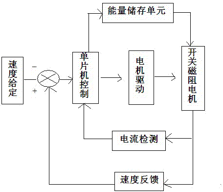
[0014] see figure 1 , the dual-voltage control switched reluctance motor, including a speed setting unit, a PID regulator, a single-chip control unit, a motor drive unit, a current detection unit, a speed feedback unit for detecting the speed of the switched reluctance motor, and the switched reluctance motor; The speed given unit, the single-chip microcomputer control unit, the motor drive unit and the switched reluctance motor are electrically connected in sequence; the current detection unit is connected between the switched reluctance motor and the single-chip microcomputer control unit, and the current detection unit detects the motor winding current of the switched reluctance motor And output the current signal to the microcontroller control unit; the speed feedback unit is connected between the switched reluctance motor and the PI regulator, the speed feedback unit detects the speed of the switched reluctance motor and feeds the speed signal back to the PI regulator; the...

Embodiment 2

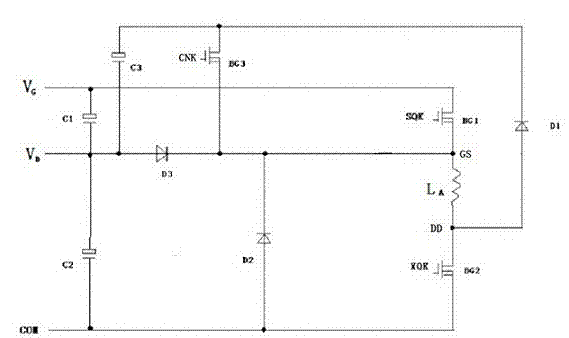
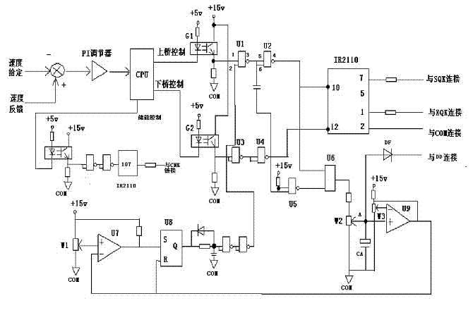
[0020] see figure 2 with image 3 , the dual-voltage control driving device of the switched reluctance motor, including the first MOS transistor BG1, the third diode D3 and a single-chip microcomputer control unit for controlling the first MOS transistor BG1 to be turned on and off; the first MOS transistor BG1 The source is connected to the positive power supply terminal of the switched reluctance motor, the drain is used to connect to the first power supply VG, the gate is connected to the single-chip control unit; the cathode of the third diode D3 is connected to the positive power supply terminal of the switched reluctance motor, and the anode Used to connect the second power supply VD. Also includes an energy storage unit, the energy storage unit includes a third MOS transistor BG3, a first capacitor C1, a second capacitor C2, a third capacitor C3, a first diode D1 and a second diode D2; the first capacitor C1 is connected between the drain and source of the MOS tube; ...


PUM


Abstract

The invention discloses a dual-voltage control switch reluctance motor. A motor drive unit comprises a first MOS (Metal Oxide Semiconductor) transistor BG1 and a third diode D3; the source electrode of the first MOS transistor BG1 is connected with the positive electrode power supply end of the switch reluctance motor, and the drain electrode of the first MOS transistor BG1 is used for being connected with a first power supply VG; the grid electrode of the first MOS transistor BG1 is connected with a gasket and a unit; the cathode of the third diode D3 is connected with the positive electrode power supply end of the switch reluctance motor; the anode of the third diode D3 is used for being connected with a second power supply VD; and the cathode power supply end of the switch reluctance motor is grounded. The dual-voltage control switch reluctance motor also comprises an energy storage unit, wherein the energy storage unit comprises a third MOS transistor BG3, a first capacitor C1, a second capacitor C2, a third capacitor C3, a first diode D1 and a second diode D2. According to the technology, the nose of the motor and the switching frequency of a power device can be reduced, thus the efficiency of the system and the reliability of a controller are improved.

Description

technical field [0001] The technology relates to a DC motor and its driving device, in particular to a dual-voltage control switched reluctance motor and its dual-voltage control driving device. Background technique [0002] At present, the control of switched reluctance motors adopts a single DC voltage, and there are three control methods, namely: angle position control, current chopping control and voltage chopping control. DC chopping is to convert a fixed DC voltage into a variable DC voltage, also known as DC / DC conversion. The basic idea of ​​chopping DC with a chopper is: if you change the operating frequency of the switch, or change the time ratio of the DC current on and off, you can change the average value of the voltage and current applied to the load. Most of the above control methods are commonly used in the prior art, such as speed control of DC motors, switching power supplies, and the like. The DC chopper uses power components to properly cut the fixed vo...

Claims


Application Information

Patent Timeline
IPC IPC(8): H02P6/06
CPCY02P80/10
Inventor 童自成
Owner NANJING YINMAO ELECTRIC AUTOMATION
Why Eureka
Try Eureka