Desulfurization and denitrification method for streamer discharge plasma free radical injected flue gas

A technology of plasma and streamer discharge, applied in separation methods, chemical instruments and methods, and separation of dispersed particles, can solve problems such as secondary pollution, high operating costs, and large consumption of reducing agents, and achieve low system resistance and low energy consumption. Low, small footprint effect

Inactive Publication Date: 2012-11-07
GUANGDONG J TECH ENVIRONMENT SCI CO LTD
View PDF3 Cites 15 Cited by
  • Summary
  • Abstract
  • Description
  • Claims
  • Application Information

AI Technical Summary

Problems solved by technology

SCR technology has problems such as expensive catalysts and easy poisoning, high operating costs; formation of sulfuric acid such as ammonium sulfate to block equipment; secondary pollution caused by ammonia leakage
The temperature required for the SNCR reaction is above 900°C and does not require a catalyst, but the consumption of the reducing agent is large, the denitrification efficiency is not high, and there is also ammonia leakage and the generation of N 2 O, CO and other secondary pollution problems

Method used


Image

  • Desulfurization and denitrification method for streamer discharge plasma free radical injected flue gas

Examples


Embodiment 1

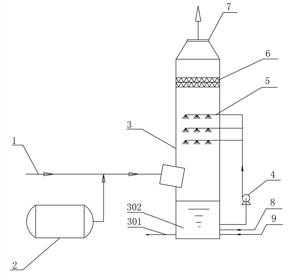
[0023] As shown in Figure 1, a method for desulfurization and denitrification by injecting streamer discharge plasma radicals into flue gas comprises the following steps: the dust-removed boiler flue gas 1 passes through the flue; in the streamer discharge plasma reactor 2, the cathode 201 and The anode 202 constitutes an electric field space, and a high-voltage power supply of 10-50kV is connected to apply a voltage between the two electrodes, and the air injected into the reactor is discharged to generate plasma radicals, and the gas containing plasma radicals is injected into the flue, Plasma free radicals oxidize part or all of sulfur oxides and nitrogen oxides into higher valence oxides (NO 2 , N 2 o 3 , N 2 o 5 , SO 3 Wait). The flue gas that has undergone the action of plasma free radicals enters the desulfurization tower 3, and the flue gas flows from bottom to top in the tower, and the NH-containing gas ejected from the spray layer 5 3 ·H 2 The circulating spra...

Embodiment 2

[0028] As shown in Figure 1, a method for desulfurization and denitrification by injecting streamer discharge plasma radicals into flue gas comprises the following steps: the dust-removed boiler flue gas 1 passes through the flue; in the streamer discharge plasma reactor 2, the cathode 201 and The anode 202 constitutes the electric field space, and the high-voltage power supply of 50-100kV is connected to discharge the oxygen injected into the reactor to generate plasma radicals, and the gas containing plasma radicals is injected into the flue, and the plasma radicals oxidize sulfur substances, nitrogen oxides are partially or fully oxidized to higher valence oxides (NO 2 , N 2 o 3 , N 2 o 5 , SO 3 Wait). The flue gas that has undergone the action of plasma free radicals enters the desulfurization tower 3, and the flue gas flows from bottom to top in the tower, and the NH-containing gas ejected from the spray layer 5 3 ·H 2 The circulating spray absorbent of O is in cou...


PUM


Abstract

The invention discloses a desulfurization and denitrification method for streamer discharge plasma free radical injected flue gas. The method comprises the following steps of: 1) discharging oxygen or air to produce plasma free radicals by using a streamer discharge plasma reactor; 2) injecting the gas containing the plasma free radicals into a flue, and mixing the gas and flue gas containing sulfur oxides and nitrogen oxides, wherein the sulfur oxides and the nitrogen oxides in the flue gas are converted into high-valent oxides by the plasma free radicals; 3) delivering the flue gas in the last step to a desulfurization tower for circular spraying absorption, so that the sulfur oxides and the nitrogen oxides enter a liquid phase; and 4) demisting the flue gas subjected to the circular spraying absorption, and discharging through a chimney. The method has synchronous desulfurization and denitrification capability; a catalyst and a special reaction temperature requirement are not required in the denitrification process; desulfurization and denitrification are integrated, so that the investment is low, and a small space is occupied; and the system is low in resistance and low in energy consumption.

Description

technical field [0001] The invention relates to a desulfurization and denitrification method for injecting streamer discharge plasma radicals into flue gas. Background technique [0002] Coal accounts for more than 75% of my country's total primary energy consumption. During the combustion of coal, a large amount of sulfur dioxide and nitrogen oxides are produced, forming acid rain and photochemical smog, which cause air pollution. According to the Bulletin of the First National Survey of Pollution Sources published by the Ministry of Environmental Protection on February 6, 2010, the emissions of sulfur dioxide and nitrogen oxides in 2007 were 23.2 million tons and 17.977 million tons. It is estimated that by 2020, my country's energy demand may reach 3 billion to 3.4 billion tons of standard coal, and the sulfur dioxide, soot, and nitrogen oxides emitted by thermal power plants will reach 21 million tons, 5 million tons, and 12 million tons. Emissions cause direct economic ...

Claims


Application Information

Patent Timeline
Patent Type & Authority Applications(China)
IPC IPC(8): B01D53/76B01D53/79B01D53/60
CPCY02A50/20
Inventor 胡小吐邓康刘勇
Owner GUANGDONG J TECH ENVIRONMENT SCI CO LTD
Why Eureka
Try Eureka