
Magnetic nanometer titanium dioxide wastewater treatment and recovery device

A nano-titanium dioxide and wastewater treatment technology, which is applied in the directions of water/sewage multi-stage treatment, light water/sewage treatment, water/sludge/sewage treatment, etc., can solve the problem of inability to recycle and recycle waste water, and high loss rate of particle photocatalysts , low catalytic efficiency and other problems, to achieve the effect of solving the difficulty of solid-liquid separation, reducing the probability of recombination, and high catalytic activity

Inactive Publication Date: 2012-11-21
杰瑞环境工程技术有限公司
View PDF7 Cites 6 Cited by
  • Summary
  • Abstract
  • Description
  • Claims
  • Application Information

AI Technical Summary

Problems solved by technology

However, titanium dioxide also has its own defects: ① Its forbidden band is wide (anatase E g =3.2eV, rutile type E g =3.02eV), can only be excited by ultraviolet light; ②Electrons and holes are easy to recombine, so the catalytic efficiency is low, the particles are small, and it is difficult to separate, which limits its application.
[0005] In the process of wastewater treatment, the particles of photocatalyst titanium dioxide are too small to be separated from the reaction mixture, resulting in a large loss rate of particle photocatalysts, which cannot be effectively recovered and recycled from the treated wastewater

Method used


Image

  • Magnetic nanometer titanium dioxide wastewater treatment and recovery device
  • Magnetic nanometer titanium dioxide wastewater treatment and recovery device

Examples


Embodiment Construction

[0019] The present invention will be further described below in conjunction with the accompanying drawings and embodiments.

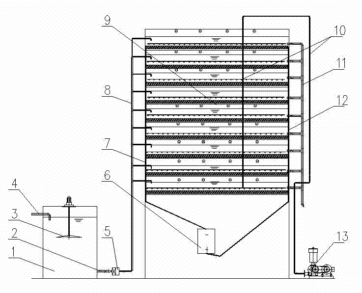
[0020] Such as figure 1 As shown, a magnetically loaded nano-titanium dioxide wastewater treatment and recovery device includes a mixing water tank 1 and a photocatalytic reaction chamber 9 .

[0021] The top of the mixing water tank is equipped with a mixer 3 , the upper part is provided with a water inlet pipe 4 , and the lower part is provided with a water outlet pipe 2 , and the water outlet pipe 2 is connected with the water inlet pipe 8 of the photocatalytic reaction chamber 9 through a water pump 5 . Printing and dyeing wastewater enters the mixing tank 1 after conventional physical, chemical and biochemical treatment, and the mixer 3 on the top of the mixing tank 1 rotates continuously for stirring and mixing, so that the wastewater and the magnetic nano-titanium dioxide photocatalyst are fully mixed, and then transported to the photocatalytic r...


PUM


Abstract

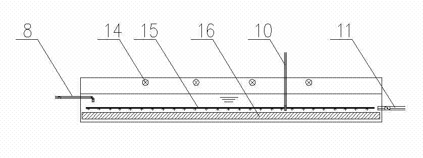
The invention relates to a magnetic nanometer titanium dioxide wastewater treatment and recovery device. The device comprises a mixed water tank and a photocatalytic reaction chamber, wherein the top of the mixed water tank is provided with a stirring machine, the upper part of the mixed water tank is provided with a water inlet tube, the lower part of the mixed water tank is provided with a water outlet tube, the water outlet tube is connected with the water inlet tube of the photocatalytic reaction chamber, the photocatalytic reaction chamber has a multi-layer structure, the upper part in each layer of the photocatalytic reaction chamber is provided with an ultraviolet lamp light source, the middle of the each layer of the photocatalytic reaction chamber is a reaction space, the lower part of each layer of the photocatalytic reaction chamber is provided with a blast aeration tube and an electromagnetic sucker, the blast aeration tube is connected with a blower, and each layer of the photocatalytic reaction chamber is also provided with an overflow tube; and two ends of the photocatalytic reaction chamber are provided with an applied electric field, and the applied electric field is formed by an anode, a cathode and a direct-current power supply. The device which adopts a novel structure of magnetic nanometer titanium dioxide and the rectangular electromagnetic sucker enables the loss rate of the nanometer titanium dioxide to be greatly reduced, a difficult solid-liquid separation problem to be solved, the repeated utilization of a resource to be realized, the treatment cost to be reduced, and resource saving and environmental protection purposes to be reached.

Description

technical field [0001] The invention relates to a water treatment device, in particular to a photocatalytic industrial wastewater treatment device. Background technique [0002] The deep purification and reuse of wastewater is the implementation method for enterprises to save energy and reduce emissions. In my country, the production of organic industrial wastewater is increasing year by year. In 1995 alone, the discharge of industrial wastewater (excluding township enterprises) in my country was 22.3 billion tons, containing 7.7 million tons of COD, 1823 tons of heavy metals, 1132 tons of arsenic, 2504 tons of cyanide, 6,366 tons of volatile phenols and 64,341 tons of petroleum, of which only 12.3 billion tons of wastewater met the discharge standards. The rest, especially high-concentration refractory organic industrial wastewater, caused serious pollution to the environment. High-concentration refractory organic industrial wastewater was mainly distributed in the chemical ...

Claims


Application Information

Patent Timeline
Patent Type & Authority Applications(China)
IPC IPC(8): C02F9/12C02F1/32
Inventor 吴佐林
Owner 杰瑞环境工程技术有限公司
Learn More