Particle source and preparation method thereof

A particle source and needle tip technology, applied in the field of particle sources, can solve the problems of uneven ion energy distribution, low resolution, small equivalent diameter, etc.

Active Publication Date: 2012-11-21
CHINA ELECTRONIC TECH GRP CORP NO 38 RES INST
View PDF6 Cites 13 Cited by
  • Summary
  • Abstract
  • Description
  • Claims
  • Application Information

AI Technical Summary

Problems solved by technology

[0004] The most commonly used electron source is the Schottky field emission electron source, which has the advantages of long life compared with the traditional thermal electron source, but the disadvantages are large equivalent diameter, low resolution, low brightness, and poor uniformity of electron energy Wait
The advantages of the cold field emission electron source, which is currently considered to be superior in performance, are that the equivalent diameter is very small, and the brightness is much higher than that of the Schottky field emission electron source at high voltage, but the brightness deteriorates sharply at low voltage, and many materials, especially biological samples Must be detected in low voltage mode to not be damaged
[0005] The gaseous field emission ion source appeared very early. The

Method used


Image

  • Particle source and preparation method thereof
  • Particle source and preparation method thereof
  • Particle source and preparation method thereof

Examples


Embodiment Construction

[0054]Preferred embodiments of the present invention are described below with reference to the accompanying drawings. It should be understood that the following embodiments are illustrative rather than exhaustive, and are only used to illustrate the principle of the present invention, but not intended to limit the scope of the present invention.

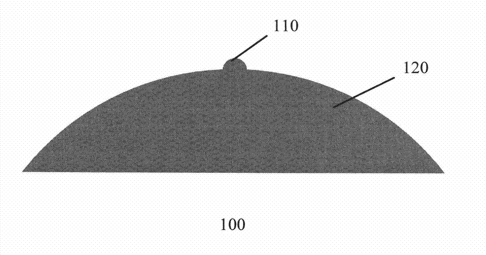
[0055] figure 1 A schematic structural diagram of a particle source 100 according to an embodiment of the present invention is shown, which can be used as an electron source or an ion source.

[0056] Such as figure 1 As shown, particle source 100 includes tip 110 and base 120 . The needle tip 110 is formed as a tiny protrusion on the base 120 . The radius of curvature at the top of the tip 110 is on the order of nanometers, and the number of atoms in the topmost layer can be at least one. The top of the base 120 forms a gentle protrusion, and is preferably symmetrical about the central axis. Preferably, the radius of curvature ...


PUM

PropertyMeasurementUnit
Melting pointaaaaaaaaaa

Abstract

The invention discloses a particle source which comprises a base and a tip, wherein the base is provided with a gradual top, and the tip is provided wih a slight bulge on the base. The particle source disclosed by the invention can provide large beam flow density and small beam flow angle.

Description

technical field [0001] The present invention relates to a particle source, more particularly to a particle source for an electron microscope, a focused ion beam, a micro-focus X-ray tube, an electron beam lithography machine, an ion beam lithography machine and a manufacturing method thereof. Background technique [0002] Imaging systems such as electron microscopes, focused ion beams, micro-focus X-ray tubes, electron beam lithography, and ion beam lithography play an important role in various fields such as micro-nano detection and manufacturing. [0003] An electron source for generating electrons and an ion source for generating ions (collectively referred to as a particle source, usually a wire) are key components of these imaging systems. The performance of the particle source ultimately determines the resolution, contrast and other important performances of the imaging system. [0004] The most commonly used electron source is the Schottky field emission electron sou...

Claims


Application Information

Patent Timeline
IPC IPC(8): H01J37/08H01J37/06H01J9/02
CPCH01J37/073H01J1/3044H01J37/08H01J9/02H01J2237/0807H01J35/065H01J9/025H01J37/06H01J37/04
Inventor 刘华荣陈娉
Owner CHINA ELECTRONIC TECH GRP CORP NO 38 RES INST
Why Eureka
Try Eureka