

Resonance rod, cavity filter and method for manufacturing resonance rod
A technology of cavity filter and manufacturing method, which is applied in the direction of resonators, waveguide devices, electrical components, etc., can solve the problems of one-time molding processing by cold heading process, etc., and achieve the effect of reducing material loss and improving processing efficiency
- Summary
- Abstract
- Description
- Claims
- Application Information
AI Technical Summary
Problems solved by technology
Method used
Image

Examples
Embodiment 1
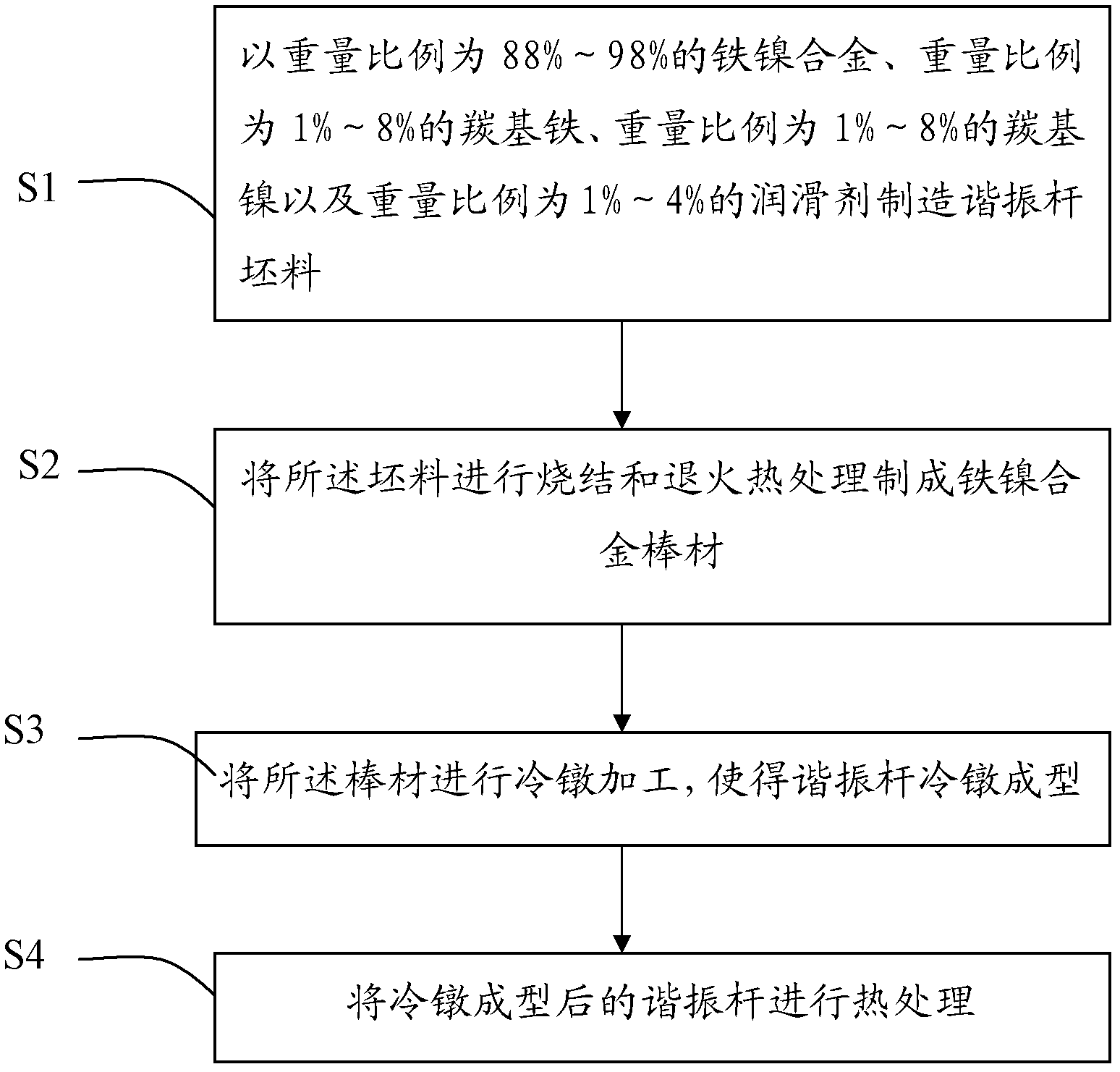
[0028] Embodiment 1: the iron-nickel alloy powder that is 98% by weight, the carbonyl iron powder that is 1%, the carbonyl nickel powder that is 1% by weight and the iron-nickel alloy powder, carbonyl The lubricant of 1% of the total amount of iron powder, carbonyl nickel powder is batching, manufactures the blank of resonant rod, and this lubricant can be stearic acid lubricant, paraffin, polyvinyl alcohol, selects stearic acid lubrication in the present embodiment In this step, pure iron with an iron content > 99.95% and pure nickel with a nickel content > 99.96% are selected, and the alloy powder containing 36% Ni prepared by ultra-high pressure water atomization technology or steam atomization technology, After dehydration, drying, sieving, raw powder high-temperature reduction, powder cake crushing, sieving, batching and other processes to obtain 36% Ni high-purity iron-nickel alloy powder. Mechanically mix the high-purity iron-nickel alloy powder with carbonyl iron powde...
Embodiment 2
[0034]Embodiment 2: be 88% steam-atomized iron-nickel alloy powder by weight ratio, be the carbonyl iron powder of 6% by weight ratio, be the carbonyl nickel powder of 6% by weight ratio and be described iron-nickel alloy powder, carbonyl The stearic acid lubricant of 4% of the total amount of iron powder and carbonyl nickel powder is used as ingredients to manufacture the blank of the resonant rod. The sintering and heat treatment aging conditions of the blank are as follows: the sintering temperature is set at 1350°C, the sintering time is set at 3 hours, the annealing temperature is set at 1050°C, and the annealing time is set at 5 hours. For the steps of manufacturing the billet and the iron-nickel alloy bar in the embodiment of the present invention, reference may be made to the description in Embodiment 1, and details are not repeated here.
[0035] After testing, the impact toughness index of the iron-nickel alloy bar is 263.5J / cm 2 , the section shrinkage rate is 68%,...
Embodiment 3
[0037] Embodiment 3: be 93% water atomization iron-nickel alloy powder with weight ratio, the carbonyl iron powder that is 4% by weight ratio, the carbonyl nickel powder that is 3% by weight ratio and the described iron-nickel alloy powder, carbonyl The stearic acid lubricant of 2% of the total amount of iron powder and carbonyl nickel powder is used as ingredients to manufacture the blank of the resonant rod. The sintering and heat treatment aging conditions of the blank are as follows: the sintering temperature is set to 1450°C, the sintering time is set to 6 hours, the annealing temperature is set to 1100°C, and the annealing time is set to 8 hours. For the steps of manufacturing the billet and the iron-nickel alloy bar in the embodiment of the present invention, reference may be made to the description in Embodiment 1, and details are not repeated here.
[0038] After testing, the impact toughness index of the iron-nickel alloy bar is 317.6J / cm 2 , the reduction of area i...
PUM
| Property | Measurement | Unit |
|---|---|---|
| reduction of area | aaaaa | aaaaa |
| reduction of area | aaaaa | aaaaa |
| reduction of area | aaaaa | aaaaa |
Abstract
Description
Claims
Application Information