Field programmable gate array-based (FPGA-based) multi-axis servo motor current loop control system and control method

A servo motor and current loop technology, applied in the FPGA-based multi-axis servo motor current loop control system and control field, can solve problems such as limited application, difficult multi-axis synchronous control, and inability for users to change

Active Publication Date: 2012-12-05
HUAZHONG UNIV OF SCI & TECH
View PDF3 Cites 46 Cited by
  • Summary
  • Abstract
  • Description
  • Claims
  • Application Information

AI Technical Summary

Problems solved by technology

[0002] Most of the currently widely used servo drivers are realized by pure software based on microprocessors such as MCU or DSP. Due to the serial execution characteristics of the software inherent in the code and the limitation of the microprocessor frequency, it is difficult to reduce it from the perspective of overall implementation. The time required to complete a sampling control is small, and the lag generated by common software-based solutions also greatly reduces the real-time performance of motor control, especially the control performance of the current loop of the servo system
Therefore, when this type of driver faces some motors with small winding inductance, it is difficult to obtain the ideal control effect due to the relatively long control hysteresis
Moreover, limited by the processing speed of the microprocessor and very limited peripheral resources, when it is necessary to build a larger control system (such as completing multi-motor cooperativ

Method used


Image

  • Field programmable gate array-based (FPGA-based) multi-axis servo motor current loop control system and control method
  • Field programmable gate array-based (FPGA-based) multi-axis servo motor current loop control system and control method
  • Field programmable gate array-based (FPGA-based) multi-axis servo motor current loop control system and control method

Examples


Embodiment Construction

[0033] In order to make the object, technical solution and advantages of the present invention clearer, the present invention will be further described in detail below in conjunction with the accompanying drawings and embodiments. It should be understood that the specific embodiments described here are only used to explain the present invention, not to limit the present invention.

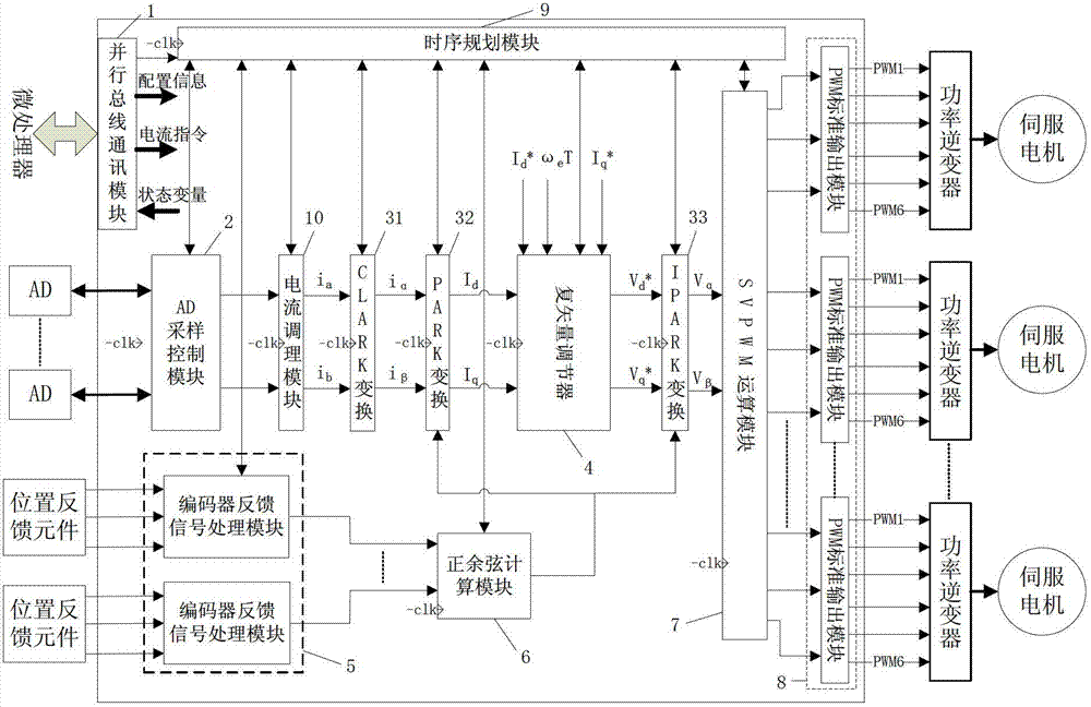
[0034] refer to figure 1 In the present invention, the control system includes a parallel bus communication module 1, an AD sampling control module 2, a vector conversion module 3, a complex vector regulator 4, an encoder feedback signal processing module 5, and a sine-cosine calculation module 6 arranged on the FPGA. SVPWM operation module 7 , PWM standard output module 8 , timing planning module 9 and current conditioning module 10 .

[0035] Parallel bus communication module 1 is used to realize communication with the microprocessor, and receive configuration information (such as regulator cont...


PUM


Abstract

The invention discloses a field programmable gate array-based (FPGA-based) multi-axis servo motor current loop control system and a control method. The control system comprises a parallel bus communication module, an analog-digital (AD) sampling control module, a vector transformation module, a complex vector adjuster, a coder feedback signal processing module, a sine-cosine calculation module, a space vector pulse width modulation (SVPWM) operation module, a pulse width modulation (PWM) standard output module, a time sequence planning module and a current modulation module, pure hardware logic is adopted to realize, and the synchronous control of a multi-axis alternative-current servo motor current loop can be independently completed; meanwhile, integrating the concept of a production line and a time division multiplexing, the invention provides a multi-axis time sequence control method, which can improve the FPGA resource utilization rate and the operation speed; and due to the adoption of the control system and the control method, while the current loop adjusting time is remarkably shortened, different application requirements such as high-speed high-precision servo drive, multi-axis synchronous drive and control of a servo motor with small winding inductance can be met.

Description

technical field [0001] The invention belongs to the field of industrial automation control, in particular to an FPGA-based multi-axis servo motor current loop control system and control method. Background technique [0002] Most of the currently widely used servo drivers are realized by pure software based on microprocessors such as MCU or DSP. Due to the serial execution characteristics of the software inherent in the code and the limitation of the microprocessor frequency, it is difficult to reduce it from the perspective of overall implementation. The time required to complete a sampling control is small, and the lag generated by common software-based solutions also greatly reduces the real-time performance of motor control, especially the control performance of the current loop of the servo system. Therefore, when this type of driver faces some motors with small winding inductance, it is difficult to obtain the ideal control effect due to the relatively long control hyst...

Claims


Application Information

Patent Timeline
IPC IPC(8): H02P21/00H02P21/22
Inventor 李叶松伍庆赵云
Owner HUAZHONG UNIV OF SCI & TECH
Why Eureka
Try Eureka