Large field-of-view bionic compound eye visual system adopting dome light cone

A bionic compound eye and vision system technology, applied in the field of bionic vision and sensing, can solve the problems of staying in the initial verification, high technical complexity, low luminous flux, etc., so as to reduce the difficulty of optical design and optimization, and solve the problem of serious imaging defocus. , the system structure is compact

Inactive Publication Date: 2012-12-12
MDTP OPTICS
View PDF2 Cites 31 Cited by
  • Summary
  • Abstract
  • Description
  • Claims
  • Application Information

AI Technical Summary

Problems solved by technology

In 2000, the Japanese research team led by J. Tanida proposed a compound eye monochromatic imaging system named TOMBO (Thin Observation Module by Bound Optics), which is a planar structure as a whole, which can realize three-dimensional imaging of the target; but each group of light The receiver only corresponds to one light collection channel, the luminous flux is low, and the planar structure also greatly inhibits the large field of view characteristics of the compound eye
In 2004, J. Tanida's team realized compound eye color imaging by adding a color filter or directly using a color CCD; but because the original TOMBO system architecture is still used, it also inherits the shortcomings of the planar compound eye structure
In 2007, the team of J. Duparre applied the design concept of side-by-side compound eyes to the curved surface structure for the first time, and proposed a spherical artificial compound eye imaging system, which uses the microlens array distributed on the curved surface to replace the planar structure, which is closer to the real compound eyes in nature and improves the edge. The imaging quality of the field of view increases the field of view; however, in order to ensure that the images of each channel are focused on the flat CCD detector, the traditional lens optical system is used, which has relatively limited improvement in imaging quality
In 2004, the research team of York University in Canada proposed the prototype "dragonfly eye" of the three-dimensional position detector based on the compound eye structure. The sub-eye channel adopts the lens-fiber bundle structure, which realizes the transmission of the sub-eye image on the spherical surface to the planar CCD detector. Imaging on the Internet can quickly detect the speed and distance of moving objects; however, "Dragonfly Eye" is still in the initial verification stage, and the technical complexity is high
In 2007, the team of J. Tanida proposed to use a compound eye imaging system based on optical fiber vision components to obtain three-dimensional images, and proposed to use the magnification of the image to estimate the distance between the system and the object; however, due to the high cost of making such components and the difficulty of assembly , so it is difficult to be popularized and applied on a large scale
It can be seen from optical analysis that if the focal points of all the sub-eyes on the curved compound eye are distributed on the same plane, the optical axes of all sub-eyes except the central sub-eye will not be perpendicular to the detector image plane, resulting in aberration increase
Even through the aspheric optimization method, it is impossible to guarantee that the focusing effect of each sub-eye can reach the ideal state
Although the beam can be converged through the deflection lens, it brings a large secondary distortion, which offsets the advantages of compound eye imaging

Method used


Image

  • Large field-of-view bionic compound eye visual system adopting dome light cone
  • Large field-of-view bionic compound eye visual system adopting dome light cone
  • Large field-of-view bionic compound eye visual system adopting dome light cone

Examples


Embodiment Construction

[0026] The present invention will be further illustrated below in conjunction with the accompanying drawings and specific embodiments. This embodiment is implemented on the premise of the technical solution of the present invention. It should be understood that these embodiments are only used to illustrate the present invention and are not intended to limit the scope of the present invention.

[0027] The following examples are preferred embodiments of the present invention:

[0028] (1) System structure composition

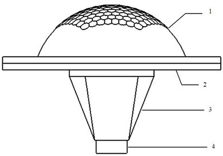
[0029] The overall structure of the compound eye optical system based on the above principles is as follows: figure 2 shown. The system includes a curved fly-eye lens 1, an aperture stop 2, a dome light cone 3, an image detector 4, and related assembly parts and an image acquisition platform connected in sequence.

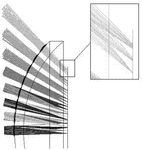
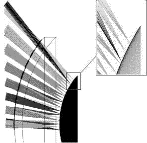
[0030] Such as figure 2 As shown, assuming that the incident light comes from infinity, the incident light from all directions within the total ...


PUM


Abstract

The invention discloses a large field-of-view bionic compound eye visual system adopting a dome light cone. The system comprises a curved surface compound eye lens, an aperture diaphragm, the light cone and an image detector, which are connected with one another in sequence; the curved surface compound eye lens comprises sub eyes and a substrate, the sub eyes are hermetically bonded in the hexagonal array mode, the surface type of the sub eyes are non-spherical, the substrate is a curved surface substrate, the aperture diaphragm is a stepped type aperture diaphragm, and the light cone is a dome light cone. According to the invention, the dome light cone coupling strategy is used as the light path conduction mode, on one hand, a curved image formed by the compound eye lens is converted into a planar image, so as to be received by a plane detector, on the other hand, the large field of view image formed by the compound eye lens is compressed into a smaller image according to an equal ratio, so that the large field of view image can be completely imaged in a small-sized detector in a lossless mode, the coupling is realized, and the technical requirements on the size of detectors are accordingly reduced.

Description

technical field [0001] [0002] The invention relates to the technical field of bionic vision and sensing. Background technique [0003] The theory of compound eye vision based on bionics has developed rapidly in recent years, and it is a frontier field integrating multiple disciplines such as mechanics, biology, optoelectronics and informatics. Because the insect compound eye vision system has the characteristics of large field of view and high detection sensitivity in principle, it has advantages that other vision systems cannot match in some military and civilian occasions (such as missile navigation, battlefield robot vision systems and intelligent aircraft, etc. People Light weight, small size, large field of view, and greater sensitivity to moving targets are expected for the entire system). The compound eye vision system can acquire original image information from different directions at the same time, which increases the field of view, and for each field of view, i...

Claims


Application Information

Patent Timeline
Patent Type & Authority Applications(China)
IPC IPC(8): G02B3/06G02B7/02G02B6/255G02B27/00
Inventor 房丰洲宋乐张姗姗张效栋张雄
Owner MDTP OPTICS
Why Eureka
Try Eureka