Composite cathode structure capable of emitting heavy current
A composite cathode, high current technology, applied in the discharge tube solid thermionic cathode, the main electrode of the discharge tube, the parts of the discharge tube/lamp, etc. Immediate response and other issues to achieve the effect of helping current emission, improving emission performance, and improving energy utilization
- Summary
- Abstract
- Description
- Claims
- Application Information
AI Technical Summary
Problems solved by technology
Method used
Image
Examples
Embodiment 1
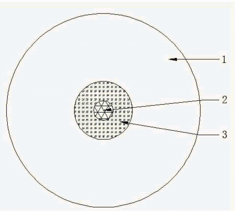
[0020] 1) as figure 1 , laying the hot cathode material 2 at the center of the cathode substrate 1 to form a circular laying area, in this embodiment, the hot cathode material 2 adopts aluminate;
[0021] 2) Lay the field emission material 3 outside the circular laying area in the center of the cathode substrate 1 to form an annular laying area. The width of the annular laying area is larger than the diameter of the circular laying area. In this embodiment, the The field emission material 3 uses carbon nanotubes;
[0022] 3) The above-mentioned metal substrate on which the cathode material is laid is placed in a hydrogen atmosphere, heated to 1200° C., maintained at a constant temperature for 2 hours, and cooled to obtain a cathode.
Embodiment 2
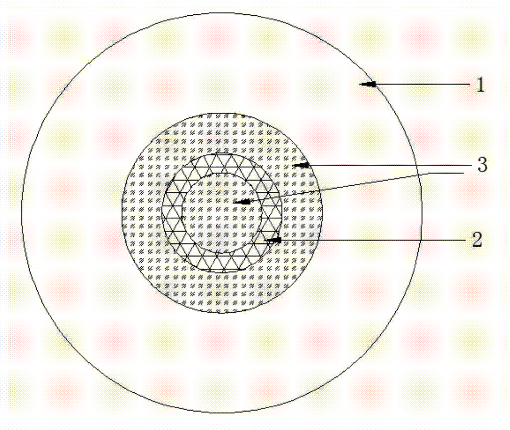
[0024] 1) as figure 2 , lay the field emission material 3 at the center position of the cathode substrate 1 and the second ring from the inside to the outside to form a circular laying area and a circular laying area. In this embodiment, the field emission material 3 is made of carbon nanotube;
[0025] 2) Lay the hot cathode material 2 at the first ring outside the circular laying area to form a circular laying area. In this embodiment, the hot cathode material 2 is aluminate, and the field emission material 3 is laid. The width of the laying area is greater than the width of the laying area where the hot cathode material 2 is laid;
[0026] 3) The above-mentioned metal substrate on which the cathode material is laid is placed in a hydrogen atmosphere, heated to 1200° C., kept at a constant temperature for 2 hours, and cooled to obtain a cathode.
Embodiment 3
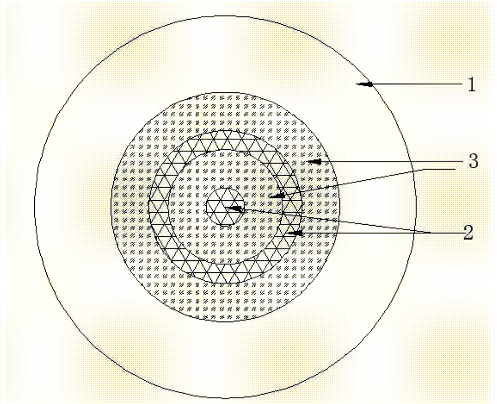
[0028] 1) as image 3 , laying the hot cathode material 2 at the center position of the cathode substrate 1 and the second ring from the inside to the outside to form a circular laying area and a ring laying area, and the hot cathode material 2 in this embodiment adopts aluminate;
[0029] 2) Lay the field emission material 3 at the first ring and the third ring outward from the circular laying area to form two ring laying areas, wherein the width of the laying area where the field emission material 3 is laid is larger than the laying heat The width of the laying area of the cathode material 2, in this embodiment, the field emission material 3 adopts carbon nanotubes;
[0030] 3) The above-mentioned metal substrate on which the cathode material is laid is placed in a hydrogen atmosphere, heated to 1200° C., maintained at a constant temperature for 2 hours, and cooled to obtain a cathode.
PUM
 Abstract
Description
Claims
Application Information
 - R&D Engineer
- R&D Manager
- IP Professional
- Industry Leading Data Capabilities
- Powerful AI technology
- Patent DNA Extraction
Browse by: Latest US Patents, China's latest patents, Technical Efficacy Thesaurus, Application Domain, Technology Topic, Popular Technical Reports.
© 2024 PatSnap. All rights reserved.Legal|Privacy policy|Modern Slavery Act Transparency Statement|Sitemap|About US| Contact US: help@patsnap.com


