

Low-ratio biomass circulating fluidized bed with cooling chamber and pollutant control method thereof
A circulating fluidized bed, low magnification technology, applied in fluidized bed combustion equipment, chemical instruments and methods, combustion methods, etc., can solve the problem of ash on the heated area
- Summary
- Abstract
- Description
- Claims
- Application Information
AI Technical Summary
Problems solved by technology
Method used
Image

Examples
specific Embodiment approach 1
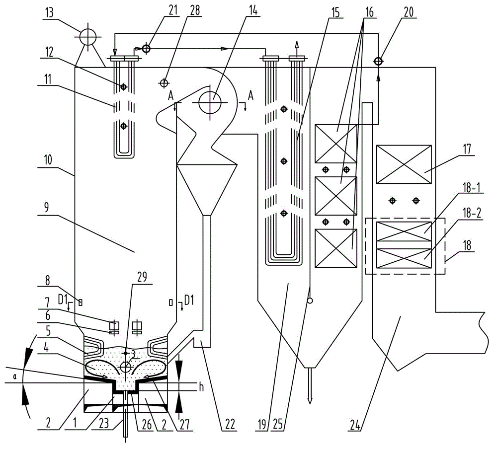
[0031] Specific implementation mode one: combine figure 1 , Figure 7 , Figure 10 and Figure 11 Explain that the low rate biomass circulating fluidized bed boiler with a cooling chamber in this embodiment includes a furnace body 10, buried pipes 5, a drum 13, a cyclone separator 14, a flue gas cooling chamber 19, and a tail shaft flue 24. Flue partition wall 25, medium temperature superheater 11, high temperature superheater 15, low temperature superheater 16, economizer 17, air preheater 18, rotating secondary tuyere 8, soot blower 12, feeder 22, First-stage desuperheater 20, second-stage desuperheater 21, SNCR (ammonia injection denitrification) nozzle 28, limestone feed port 29, middle air chamber 1, side air chamber 2, middle air distribution plate 26, side air distribution Plate 27 and slag discharge pipe 23, the drum 13 is arranged on the top of the body of furnace 10,
[0032] The flue gas cooling chamber 19 is vertically provided with a flue partition wall 25, th...
specific Embodiment approach 2
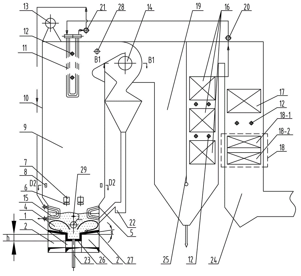
[0034] Specific implementation mode two: combination diagram 2-1 , Figure 2-2 , Figure 8 , Figure 10 and Figure 11 To illustrate, the low rate biomass circulating fluidized bed boiler with a cooling chamber in this embodiment includes a furnace body 10, a cyclone separator 14, a flue gas cooling chamber 19, a buried pipe 5, a tail shaft flue 24, and a flue Partition wall 25, medium temperature superheater 11, high temperature superheater 15, low temperature superheater 16, economizer 17, air preheater 18, rotating secondary tuyere 8, drum 13, soot blower 12, feeder 22, First-stage desuperheater 20, second-stage desuperheater 21, SNCR nozzle 28, limestone feed port 29, middle air chamber 1, side air chamber 2, middle air distribution plate 26, side air distribution plate 27 and slag discharge The pipe 23 and the drum 13 are arranged on the top of the furnace body 10;
[0035] The flue gas cooling chamber 19 is vertically provided with a flue partition wall 25, the top...
specific Embodiment approach 3
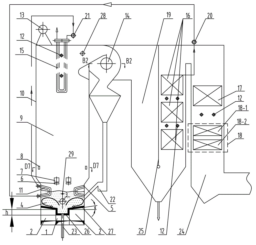
[0037] Specific implementation mode three: combination Figure 3-1 , Figure 3-2 and Figure 9-Figure 11 Explain that the low rate biomass circulating fluidized bed boiler with a cooling chamber in this embodiment includes a furnace body 10, a buried pipe 5, a cyclone separator 14, a flue gas cooling chamber 19, a tail shaft flue 24, and a flue Partition wall 25, medium temperature superheater 11, high temperature superheater 15, low temperature superheater 16, economizer 17, air preheater 18, rotating secondary tuyere 8, drum 13, soot blower 12, feeder 22, First-stage desuperheater 20, second-stage desuperheater 21, SNCR nozzle 28, limestone feed port 29, middle air chamber 1, side air chamber 2, middle air distribution plate 26, side air distribution plate 27 and slag discharge The pipe 23 and the drum 13 are arranged on the top of the furnace body 10;
[0038]The flue gas cooling chamber 19 is vertically provided with a flue partition wall 25, the top of the flue gas par...
PUM
 Abstract
Description
Claims
Application Information