Method for preparing indium target metal film

A metal thin film, indium target technology, applied in metal material coating process, final product manufacturing, sustainable manufacturing/processing, etc., can solve the problems of slow metal thin film coating rate, rough surface of precursors, low production efficiency, etc. To achieve the effect of reducing surface roughness and uniform composition

Active Publication Date: 2013-02-13
赣州市创发光电科技有限公司
View PDF4 Cites 2 Cited by
  • Summary
  • Abstract
  • Description
  • Claims
  • Application Information

AI Technical Summary

Problems solved by technology

[0004] Although the sputtering precursor and selenization process are the absorbing layer process methods that can be mass-produced and large-area, the deposition rate of the indium precursor metal film is very slow, and the production efficiency is very low, which is the problem in the production of CIGS film.
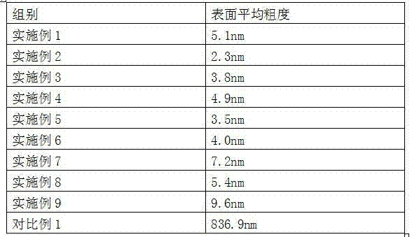
Generally, these metal thin films containing indium precursors are designed regardless of single element or alloy metal. Due to the material properties, agglomeration is easy to occur during the process, and the melting point is low, resulting in rough surface of the precursor and poor process stability, so that subsequent preparations When absorbing the layer, its surface roughness is very high, and the inhomogeneity of the composition of the absorbing layer is caused by the surface undulation of the rough precursor metal film

Method used


Image

  • Method for preparing indium target metal film

Examples


Embodiment 1

[0012] A method for preparing an indium target metal thin film, adding copper with an atomic percentage of 2% to indium metal to make a target with a diameter of 3 inches for the sputtering process, and putting the required coated glass substrate into the sputtering chamber In the body, the background pressure of the sputtering chamber was evacuated to 0.7×10 by a vacuum pumping system. -5 After torr, argon is used as the working gas, and argon is introduced through the throttle valve to control the working pressure of the sputtering chamber to be 1×10 -2 torr, a sputtering process was performed for 60 minutes with a DC power of 100 watts to prepare a planarized indium metal film.

Embodiment 2

[0014] A method for preparing an indium target metal thin film, adding copper with an atomic percentage of 6% to indium metal to make a target with a diameter of 3 inches for the sputtering process, and putting the required coated glass substrate into the sputtering chamber In the body, the background pressure of the sputtering chamber was evacuated to 0.8×10 by a vacuum pumping system. -5 After torr, argon is used as the working gas, and argon is introduced through the throttle valve to control the working pressure of the sputtering chamber to be 1×10 -2 torr, a sputtering process was performed for 60 minutes with a DC power of 100 watts to prepare a planarized indium metal film.

Embodiment 3

[0016] A method for preparing an indium target metal film, adding copper with an atomic percentage of 10% to indium metal to make a target with a diameter of 3 inches for the sputtering process, and putting the required coated glass substrate into the sputtering chamber In the body, the background pressure of the sputtering chamber was evacuated to 0.9×10 by a vacuum pumping system. -5 After torr, argon is used as the working gas, and argon is introduced through the throttle valve to control the working pressure of the sputtering chamber to be 1×10 -2 torr, a sputtering process was performed for 60 minutes with a DC power of 100 watts to prepare a planarized indium metal film.


PUM


Abstract

The invention discloses a method for preparing indium target metal film. One or more metal solid solutions or alloys with melting points being higher than that of indium are added into the indium metal, thus the physical property of the indium is changed and the physical vapordeposit method of the indium is improved, the surface roughness of a precursor metal film is greatly reduced, the surface roughness of an absorption layer can be reduced in a selenylation and sulphidation process of the precursor metal film, so that the absorption layer is uniform in components and meets the requirement of production.

Description

technical field [0001] The invention relates to a method for a metal thin film, in particular to a method for preparing an indium target metal thin film. Background technique [0002] The multi-component compound solar cell composed of group I-group III-group IV is one of the most popular materials at present. Among them, group I is copper (Cu), silver (Ag), gold (Au), group III is aluminum (Al ), gallium (Ga), indium (In), and group IV is sulfur (S), selenium (Se), and antimony (Te). The preparation methods of the layer vacuum process are divided into two categories: 1. co-evaporation; 2. sputtering precursor and selenization process. [0003] The sputtering process has the advantages of high yield, good uniformity, and easy composition control. In the sputtering precursor and selenization process, these metal films are called precursors before they react with selenium or sulfur to form an absorbing layer. The substances can come from the different composition ratios of m...

Claims


Application Information

Patent Timeline
IPC IPC(8): C23C14/34C23C14/06H01L31/18
CPCY02P70/50
Inventor 黄信二
Owner 赣州市创发光电科技有限公司
Why Eureka
Try Eureka