Immersion type fluid analytical device and debugging method thereof

A technology of fluid analysis and analysis equipment, applied in the direction of analyzing materials, material analysis by optical means, measuring devices, etc., can solve the problems of inconvenient production and maintenance, increase production cost, device dispersion, etc., to prevent collision damage or accident The effect of downtime, low cost, compact device

Inactive Publication Date: 2013-02-27
于志伟
View PDF9 Cites 3 Cited by
  • Summary
  • Abstract
  • Description
  • Claims
  • Application Information

AI Technical Summary

Problems solved by technology

[0006] 1. The volume is large. The above-mentioned spectrometers are all independent modules, which are installed in a large cabinet together with the control system and flow system;
[0007] 2. Devices are scattered, making production and maintenance inconvenient
[0008] 3. High cost, complex flow system, independently designed spectrometer, and large-volume cabinets all increase production costs

Method used


Image

  • Immersion type fluid analytical device and debugging method thereof
  • Immersion type fluid analytical device and debugging method thereof
  • Immersion type fluid analytical device and debugging method thereof

Examples


Embodiment 1

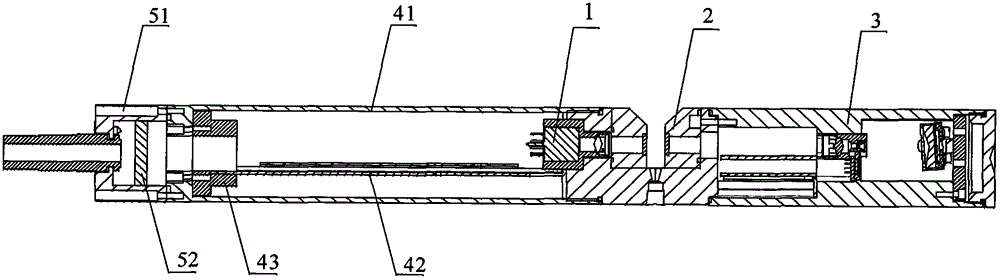
[0052] figure 1 The basic structural diagram of the immersion fluid analysis equipment of the embodiment of the present invention is schematically given, as figure 1 As shown, the immersion fluid analysis equipment includes

[0053] A light source 1, the light emitted by the light source 1 has measurement light corresponding to the absorption spectrum line of the fluid to be measured; such as xenon lamp, deuterium lamp and other broad-spectrum light sources.

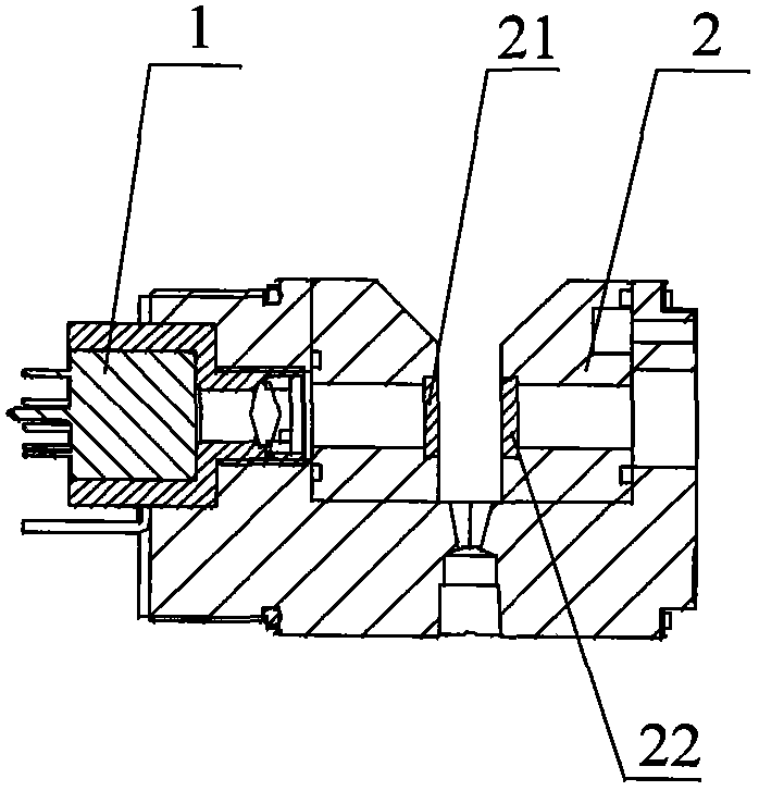
[0054] A measuring pool 2, the measuring pool is located between the light source and the optical module, and is used to contain the fluid to be measured when immersed;

[0055] figure 2 The basic structural diagram of the preferred measuring cell of the embodiment of the present invention is schematically given, as figure 2 As shown, the measuring cell 2 is in a "concave" shape and has optical windows 21, 22. There is a free space between the optical windows 21, 22. The fluid to be measured enters the free space, and...

Embodiment 2

[0079] According to the application example of the fluid analysis equipment and its debugging method described in Embodiment 1 in the continuous monitoring of flue gas, in this application example, the light source adopts a xenon lamp, and the emitted light has an absorption spectrum corresponding to nitric oxide and sulfur dioxide For the measurement light of the line, the lens group is used as the converging part, the grating is used as the spectroscopic part, and the detector adopts CMOS. The measuring pool is in a "concave" shape, and glass windows are arranged on both sides of the middle concave part to isolate the flue gas to be measured from the inner parts of the cavity, and the measurement optical path is between the windows. The light source and the converging lens are located on both sides of the window, so that the light emitted by the light source passes through the window and the smoke to be measured is converged at the slit by the converging lens.

[0080] In or...

Embodiment 3

[0086] According to the application example of the fluid analysis equipment and its debugging method described in Embodiment 1 in water quality analysis, in this application example, the light source is a xenon lamp, the lens group is used as a converging component, the grating is used as a spectroscopic component, and the detector is a CCD. The measuring pool is in a "concave" shape, and glass windows are arranged on both sides of the middle concave part to isolate the flue gas to be measured from the inner parts of the cavity, and the measurement optical path is between the windows. The light source and the converging lens are located on both sides of the window, so that the light emitted by the light source passes through the window and the water sample to be tested is converged at the slit by the converging lens.

[0087] In order to further adjust the measurement accuracy and range of the analysis equipment, the lens group and the slit are arranged in the first cavity thro...


PUM

PropertyMeasurementUnit
Lengthaaaaaaaaaa
Diameteraaaaaaaaaa

Abstract

The invention discloses an immersion type fluid analytical device. The device comprises a light source, a measuring cell, an optical module and an electronic module and further comprises a first cavity, a convergence component, a slit, a light split component, a photoelectric detection component and an end cover, wherein the hollow first cavity is arranged on one side of the measuring cell and maintains sealed with the measuring cell; the convergence component is arranged in the first cavity and used for converging measuring lights which are emitted by the light source and penetrate through the measuring cell at the slit; the slit is arranged in the first cavity and on one side of the convergence component; the light split component is arranged in the first cavity through an installing part; the photoelectric detection component is arranged in the first cavity and used for converting the measuring light signals which penetrate the slit and are light-split by the light split component into electric signals and sending the signals to the electronic module; and the end cover is arranged on one side of the first cavity and maintains sealed with the first cavity. The invention further discloses a debugging method of the fluid analytical device. The device and the method have the advantages of being compact in structure, convenient to maintain, low in cost, comprehensive in functions and the like.

Description

technical field [0001] The invention relates to gas or liquid analysis, in particular to an immersion type fluid analysis equipment and a debugging method thereof. Background technique [0002] With the development of society and the improvement of living standards, people pay more and more attention to their own living environment, and gradually increase their attention to the quality of air, drinking, food, etc. As a high-precision, fast, and low-power analysis technology, spectral analysis technology, such as absorption spectrum analysis technology, can be widely used in continuous analysis of flue gas and water quality. [0003] In flue gas analysis, sampling method and in-situ method are usually used. Among them, the analysis process of the sampling method is as follows: the flue gas to be measured in the flue is sampled by an air pump, and then sent into the heated gas chamber, the light emitted by the light source passes through the flue gas to be measured in the flu...

Claims


Application Information

Patent Timeline
IPC IPC(8): G01N21/25G01N21/31G01N21/01
Inventor 于志伟
Owner 于志伟
Why Eureka
Try Eureka