Method for manufacturing solar cell

A solar cell and manufacturing method technology, applied in the direction of final product manufacturing, sustainable manufacturing/processing, circuits, etc., can solve the problems of inability to identify the electrode window with the naked eye, defective rate, increased production cost, and complicated process, and achieve low cost , Simple and cost-effective, the effect of increasing the doping concentration

Inactive Publication Date: 2013-02-27
NANTONG UNIVERSITY
View PDF4 Cites 11 Cited by
  • Summary
  • Abstract
  • Description
  • Claims
  • Application Information

AI Technical Summary

Problems solved by technology

[0005] The process of this method is relatively complicated, requiring multiple depositions on the surface of the silicon wafer, and after removing the phosphosilicate glass and the masking layer; if there is no alignment mark, the

Method used


Image

  • Method for manufacturing solar cell
  • Method for manufacturing solar cell

Examples


Embodiment Construction

[0025] The purpose and effects of the present invention will become more apparent by referring to the accompanying drawings in detail of the present invention.

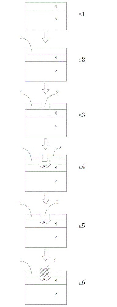
[0026] Such as figure 1 As shown, the solar cell manufacturing method of this embodiment includes the following steps:

[0027] a1. Pre-doping the P-type silicon wafer substrate with a resistivity of 3Ω m after texturing to form a P-N junction; the pre-doping concentration is 10 16 / cm 3 , the pre-doping time is 60min, and the pre-doping temperature is 900°C.

[0028] a2. A layer of silicon nitride layer 1 is deposited on the surface of the silicon wafer. The silicon nitride layer 1 is used as a masking layer for selective doping and also as an anti-reflection layer of the solar cell.

[0029] a3. Open the electrode window 2 on the surface of the silicon wafer by laser etching.

[0030] a4. Use phosphorus-doped silicon dioxide to perform secondary deposition on the surface of the silicon wafer, and at the same tim...


PUM

PropertyMeasurementUnit
Resistivityaaaaaaaaaa

Abstract

The invention relates to a method for manufacturing a solar cell. The etching ratio of hydrofluoric acid buffer solution to silica and silicon nitride is skillfully utilized to keep a silicon nitride masking layer as an anti-reflection layer of the cell, therefore, the anti-reflection layer is not needed to be independently manufactured before sintering an electrode, the process is simplified, and the production efficiency is improved. The method utilizes good blocking performance of the silicon nitride to impurities to well solve a problem that the solar cell is selectively doped, thus improving doping density of an area lower than the metal electrode, reducing series resistance, reducing the deposing density of the area outside the electrode, reducing composition of photon-generated carriers and improving short-circuit current. The non-sacrificial silicon nitride masking layer is used for preventing other impurity elements from diffusing to a silicon wafer and using a silicon nitride etching slot in the process as an alignment mark of a main grid line, so that the alignment during the production is simpler.

Description

technical field [0001] The invention relates to a method for manufacturing a solar cell. Background technique [0002] Since the 1950s, people have developed a variety of solar cell structures and process preparation methods, such as laser-grooved buried grid cells, screen-printed cells, high-efficiency rear point-contact electrode cells, textured cells, etc., to improve solar energy. The efficiency of the battery. The efficiency of solar cells has increased from the initial few percentage points to more than 18% of the current crystalline silicon cells. Silicon-based solar cells have become the world's main source of clean energy. However, the efficiency of solar cells cannot meet people's needs. In order to better promote the application of solar cells, new preparation processes and cell structures must be studied to improve cell efficiency. And selective doping solar cell (Selective emitter solar cell, SE solar cell) is one of the new methods to achieve high efficiency...

Claims


Application Information

Patent Timeline
IPC IPC(8): H01L31/18
CPCY02P70/50
Inventor 花国然王强张竹青曹海平周雨薇朱海峰居志兰
Owner NANTONG UNIVERSITY
Why Eureka
Try Eureka