Reactive conductive pressure-sensitive adhesive tape

A conductive tape, reactive technology, used in conductive adhesives, circuits, adhesives, etc., can solve problems such as inability to provide processing strength, and achieve the effect of improving electrical reliability and reducing the number of

Inactive Publication Date: 2013-09-18
ADHESIVES RES
View PDF6 Cites 11 Cited by
  • Summary
  • Abstract
  • Description
  • Claims
  • Application Information

AI Technical Summary

Problems solved by technology

Pastes do not provide sufficient handl

Method used


Image

  • Reactive conductive pressure-sensitive adhesive tape
  • Reactive conductive pressure-sensitive adhesive tape
  • Reactive conductive pressure-sensitive adhesive tape

Examples


Embodiment 1

[0041] Example 1 illustrates an embodiment of a reactive conductive PSA based on a curable acrylic base polymer and a free radical curable crosslinking component. The pressure sensitive adhesive composition was formulated as described in Table 1, where parts are by weight.

[0042] Table 1

[0043] project description

Quantity (ppH)

Epoxy, carboxylic acid functional acrylic polymer

41.0

Hydrophobic aliphatic urethane acrylate oligomer

3.7

Urethane Acrylate Oligomer

10.3

Dibenzoyl peroxide

0.1

Silver-coated nickel particles

21.9

ethyl acetate

23.0

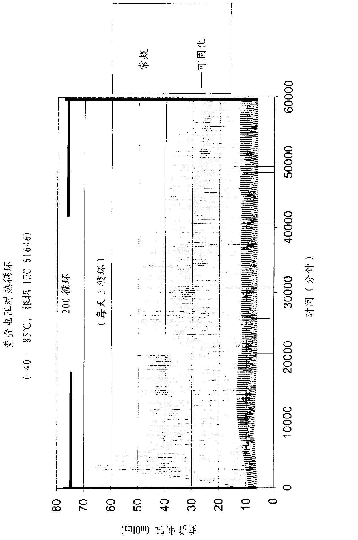
[0044] The glass transition temperature (T g ) at -23°C in the uncured state, T in the cured state g is -24°C, which is favorable for reliable performance during thermal cycling that occurs in photovoltaic cells used under harsh conditions. low T g The flexible adhesive deforms and compensates for stresses developed during thermal cycling and ...

Embodiment 2

[0059]Example 2 illustrates a reactive conductive PSA formed from a hydroxyl functional acrylic PSA polymer base resin and a blocked isocyanate crosslinking component. A solvent-borne conductive PSA was formed by combining a hydroxyl-functional acrylic polymer (27 g, 90 parts by weight ethylhexyl acrylate, 10 parts by weight hydroxyethyl acrylate, Mn ~ 250K, Mw ~ 550K) and blocked isocyanate Solution Trixene BI-7982 (4 g, DMP-terminated HDI trimer from Baxenden Chemical) was dissolved in ethyl acetate (70 g). To this solution, nominally 35 μm Ag-coated glass beads (15 g, Conduct-O-Fil TP35-S12 from Potters Industries) were added slowly and stirred using a mechanical paddle mixer.

[0060] This solution was coated on a 2 mil PET release liner using a bar drawdown coater and dried at 65°C for 5 minutes to form a film about 38 μm thick, giving a tacky, Uncured PSA film.

[0061] This film was laminated to a 36 micron tin-coated copper foil substrate using a lamination pressure ...

Embodiment 3

[0063] Like Example 2, Example 3 is another example of a reactive conductive PSA formed from a hydroxyl functional acrylic PSA polymer base resin and a blocked isocyanate crosslinking component. A curable conductive PSA similar to that described in Example 2 was formulated by combining a hydroxy-functional acrylic PSA base resin (8.9 g polymer in 13.4 g ethyl acetate solvent), Dimethylpyrazole (DMP)-hexamethylene diisocyanate (HDI) trimer adduct blocked isocyanate curing agent (1.1 g adduct in 1.1 g methyl ethyl ketone solvent), and Ag Coated glass beads (2.1 g) and stirred using a vortex mixer. This adhesive was coated onto a release liner using a drawdown bar and dried in a convection oven to give a 1.7 mil thick dried adhesive film. This film was laminated to a Sn-coated Cu foil backing using a lab roll.

[0064] One inch wide strips of this laminate were cut, the release liner was removed, and the strips were laminated to stainless steel test panels according to PSTC met...


PUM

PropertyMeasurementUnit
Glass transition temperatureaaaaaaaaaa

Abstract

A reactive pressure sensitive adhesive composition is disclosed. A tape formed using the reactive pressure sensitive adhesive is also disclosed. In its cured state, the pressure sensitive adhesive shows superior mechanical and electrical properties compared to conventional, non-curable charge collection tapes. The tape has a cure profile pre-selected to correspond to that of a photovoltaic cell fabrication process, such that curing can take place during cell fabrication and may occur simultaneously with one or more other curing steps employed in cell fabrication.

Description

[0001] Cross References to Related Applications [0002] This application claims priority to US Application 61 / 416,385, filed November 23, 2010, which is hereby incorporated by reference in its entirety. Background technique [0003] Conductive adhesives can be used to form electrical interconnections between two conductive materials. Such adhesives have many applications, including electrical grounding of handheld devices, electromagnetic shielding, and die attach adhesives. For many of these applications, a conductive paste or conductive film may be used, depending on the specific properties and application details. [0004] However, in any conductive joint, whether formed from conductive adhesives or other materials, electrical reliability is an issue. Stable electrical properties should be exhibited over long periods of time, even under exposure to harsh conditions that can be achieved through accelerated conditioning using bias humidity testing, damp heat aging, and the...

Claims


Application Information

Patent Timeline
IPC IPC(8): C09J9/02C09J7/22C09J7/28
CPCC08K3/04C08K3/08C09J9/02C09J2203/322C09J2400/163C09J2433/00Y02E10/50C09J7/22C09J7/28C09J7/385Y10T428/2896Y10T428/2857Y10T428/287Y10T428/252Y10T428/2887Y10T428/256Y10T428/2874Y10T428/2891Y10T428/2852Y10T442/10H01L31/022425H01L31/0512C09J2301/314C09J2301/408C09J7/29
Inventor D.赫尔B.A.哈金斯
Owner ADHESIVES RES
Why Eureka
Try Eureka