Supercharge Your Innovation With Domain-Expert AI Agents!

Input/output circuit with self electronic static discharge (ESD) protection function

An input and output circuit, ESD protection technology, applied in emergency protection circuit devices, emergency protection circuit devices for limiting overcurrent/overvoltage, circuits, etc., can solve the problem that the output tube design is difficult to achieve ESD protection capability, ESD current leakage It can improve the ESD protection ability, reduce the chip area, and reduce the turn-on voltage.

Active Publication Date: 2015-04-22
西安西岳电子技术有限公司
View PDF5 Cites 0 Cited by
  • Summary
  • Abstract
  • Description
  • Claims
  • Application Information

AI Technical Summary

Problems solved by technology

If the design of the output ESD protection tube is improper, there is a risk of thermal breakdown due to the output tube being turned on before the ESD protection tube to discharge the ESD current
At the same time, in order to ensure that the output circuit has a certain driving capability, the size of the output MOS transistor is usually relatively large. If a large-sized output ESD protection circuit is added, it will occupy a very large chip area and greatly increase the cost.
[0005] When the circuit has both input and output functions, the input and output can share the ESD protection circuit. Since the output circuit usually has a certain current driving capability, the size of the output tube will be larger, and the output tube can be used for ESD protection. However, if Improper design of the output tube is difficult to achieve the required ESD protection capability
If the current driving capability of the output tube is small, the size of the output tube will be small, and ESD protection cannot be performed, and an additional ESD protection circuit needs to be added, which will not only increase the chip area and increase the cost, but also have the output tube prior to ESD protection. The danger of thermal breakdown due to the opening of the tube for ESD current discharge

Method used


Image

  • Input/output circuit with self electronic static discharge (ESD) protection function
  • Input/output circuit with self electronic static discharge (ESD) protection function
  • Input/output circuit with self electronic static discharge (ESD) protection function

Examples


Embodiment Construction

[0043] The implementation and working principle of the present invention will be further described in detail below in conjunction with the accompanying drawings, which are for explanation but not limitation of the present invention.

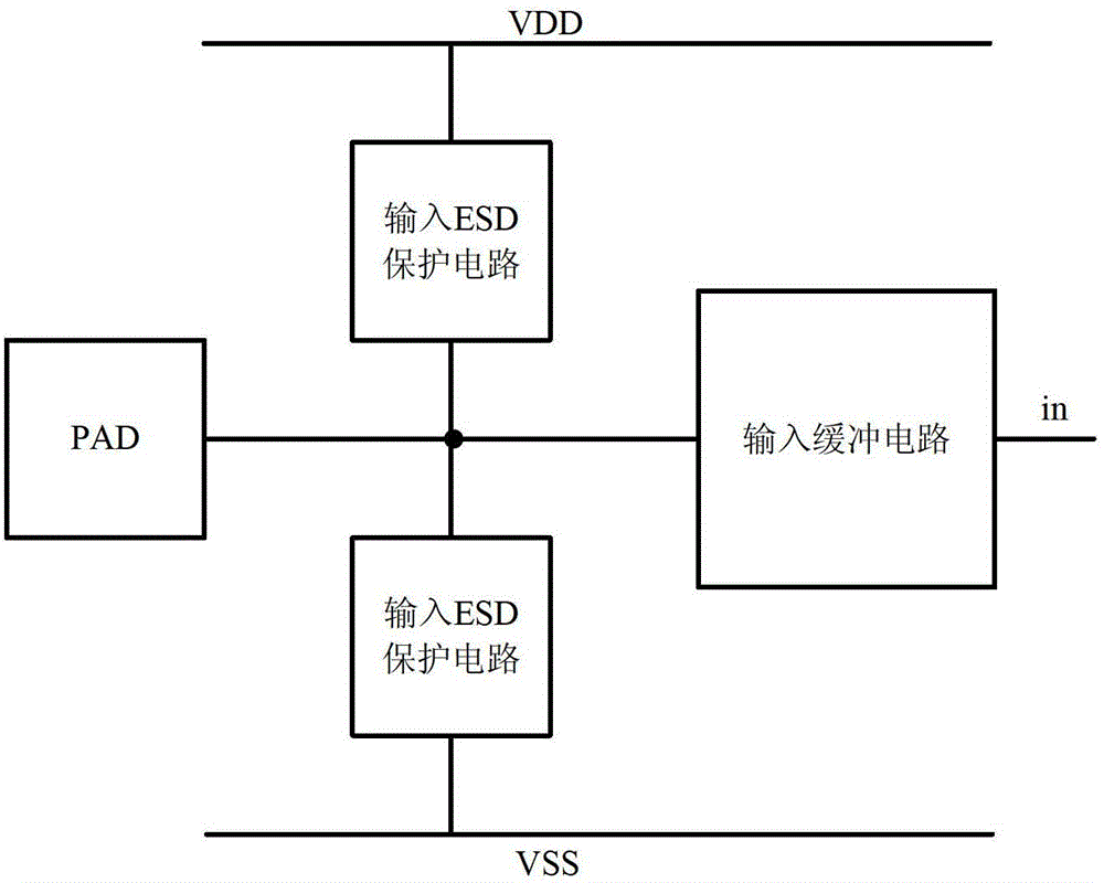
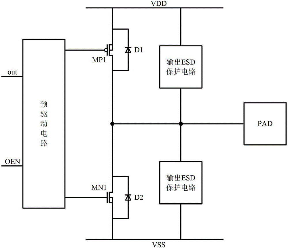
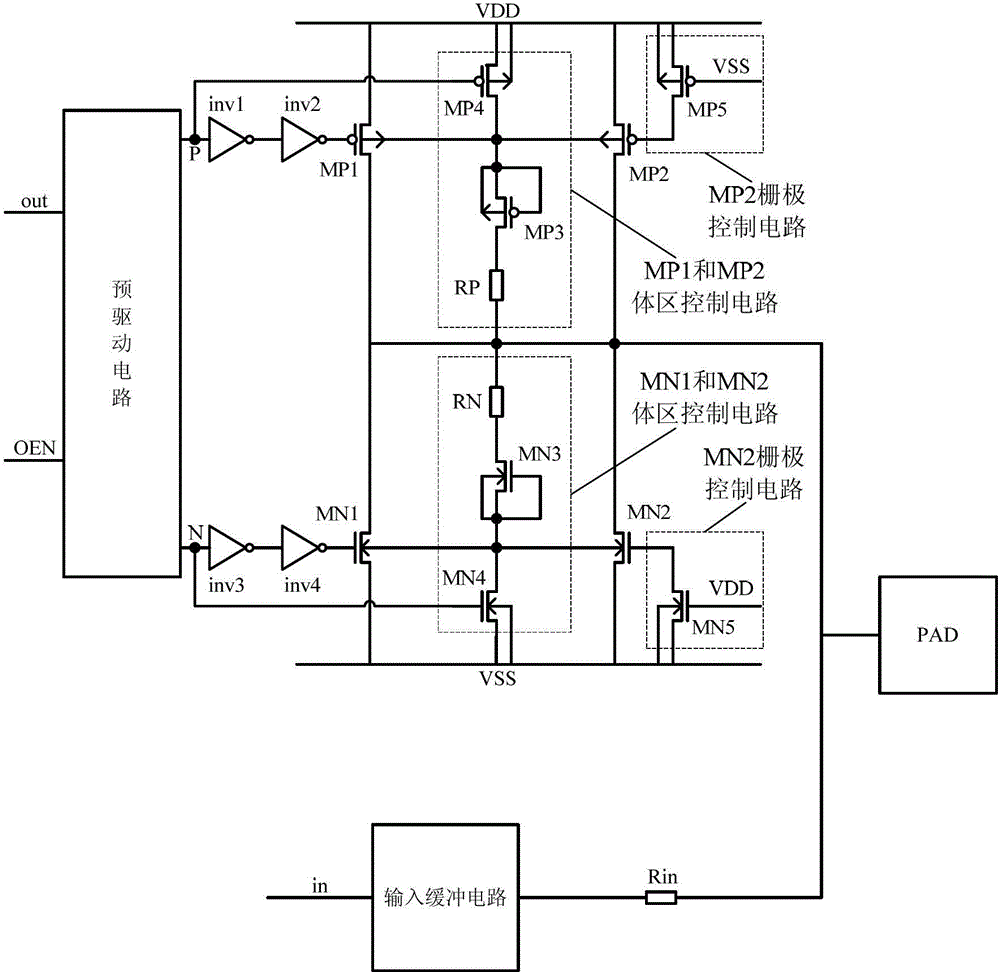
[0044] An input and output circuit with self-ESD protection, including:

[0045] Power supply VDD, ground VSS, input isolation resistance Rin, pre-drive circuit, internal output signal out, output control terminal OEN, input internal signal in, input and output PAD and ESD protection circuit;

[0046] The ESD protection circuit includes an output drive tube, an auxiliary protection tube, a body area control circuit and an auxiliary protection tube control circuit; the output drive tube and the auxiliary protection tube are connected in parallel, the output tube and the auxiliary protection tube perform self-ESD protection, and the body area control circuit controls the output And auxiliary protection tube for auxiliary triggering;

[0047] The output dri...


PUM


Abstract

The invention discloses an input / output circuit with a self electronic static discharge (ESD) protection function. The input / output circuit is led to have the ESD protection function by being additionally provided with a body region control circuit, an auxiliary protection tube and an auxiliary protection tube control circuit. Compared with other input / output circuits, the input / output circuit is not needed to be additionally provided with an ESD protection circuit and saves cost due to the fact that the area of a chip is reduced. A circuit designer can flexibly use or omit the auxiliary protection tube and the auxiliary protection tube control circuit according to the practical size of an output tube. The input / output circuit is not limited by the manufacture process and can be widely applied to the bulk silicon complementary metal-oxide-semiconductor transistor (CMOS) process and the silicon on insulator (SOI) CMOS process.

Description

Technical field [0001] The invention belongs to the technical field of electrostatic discharge protection in semiconductor integrated circuits, and relates to an input and output circuit with self-ESD protection. Background technique [0002] With the continuous progress of integrated circuit manufacturing technology, the length of polysilicon gate is getting smaller and smaller, the thickness of gate oxide is getting thinner, and the junction depth is getting shallower and shallower. Gate oxide breakdown and PN junction caused by electrostatic discharge (ESD) Problems such as thermal breakdown, interconnection burnout and potential damage are becoming more and more serious. ESD has become a reliability problem that needs to be solved urgently in the field of integrated circuits. Therefore, ESD protection circuits have become the hotspot and focus of CMOS integrated circuit reliability research. In order to ensure the ESD protection capability of CMOS integrated circuits, it is u...

Claims


Application Information

Patent Timeline
Patent Type & Authority Patents(China)
IPC IPC(8): H02H9/02H01L27/02
Inventor 王忠芳唐威杨凌尹飞王鹏包谦
Owner 西安西岳电子技术有限公司
Features
  • R&D
  • Intellectual Property
  • Life Sciences
  • Materials
  • Tech Scout
  • Unparalleled Data Quality
  • Higher Quality Content
  • 60% Fewer Hallucinations
Learn More