Laminated glass board
A glass plate, thin layer technology, applied in windshields, glass/slag layered products, layered products, etc., to achieve the effect of improving mechanical properties, better brightness, and stable performance
- Summary
- Abstract
- Description
- Claims
- Application Information
AI Technical Summary
Problems solved by technology
Method used
Image
Examples
Embodiment 1
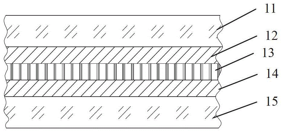
[0042] Schematic reference figure 2 , Take the first glass plate 11 and the second glass plate 15 of suitable size, and use a combination of green glass + green glass.
[0043] Cut out two PVB layers 12 and 14 and the LED chip film 13 of appropriate size, the PVB thickness is 0.76 mm, and the LED chip film 13 is 0.1 mm thick. The second glass plate 15, the second PVB layer 14, the LED chip film 13, the first PVB layer 12, and the first glass plate 11 are sequentially stacked, and circuit wires are drawn out to form a semi-finished laminated glass. Pressing in accordance with the laminated glass sheet technology to obtain the final laminated glass plate 1.
[0044] When the laminated glass plate is connected to 12V direct current, its brightness is better than that of ordinary incandescent lamp type car ceiling lights, or equivalent to other LED type car ceiling lights of the same power.
Embodiment 2
[0046] Schematic reference Figure 4 , Take the first glass plate 11 and the second glass plate 15 of suitable size, and use a combination of green glass + green glass.
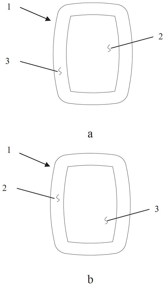
[0047] The light-emitting area 2 is planned on the glass surface of the second glass plate 15 facing the second PVB layer 14, and the YAG base material is doped with Ce 3+ Phosphor. Add this phosphor to the adhesive solution composed of transparent epoxy resin E128, curing agent DICY, accelerator 2MI, solvent acetone, etc., mix and stir evenly, coat it on the glass surface, and heat it to form a thickness of 360 nm coating. Before applying the phosphor-containing adhesive to the light-emitting area 2 of the second glass plate 15, the non-light-emitting area 3 of the area other than the area needs to be shielded with a shield, and the mixed phosphor is selected by screen printing. The adhesive solution is printed on a designated area to form a thin layer of phosphor 21, which can be covered with a protective fil...
Embodiment 3
[0051] Schematic reference Figure 5 , Take the first glass plate 11 and the second glass plate 15 of suitable size, and use a combination of white glass + white glass.
[0052] The light-emitting area 2 is planned on the glass surface of the second glass plate 15 facing the second PVB layer 14 and the glass surface of the first glass plate 11 facing the first PVB layer 12. The light-emitting areas 2 on both glass surfaces are A thin layer of phosphor 21 is placed on the two glass plates. The phosphor coating positions on the two glass plates are mirror-symmetrical, using Y 2 O 2 S matrix material doped with Eu 3+ Phosphor. Add this phosphor to the adhesive solution consisting of hard monomer methyl methacrylate, soft monomer butyl acrylate, adhesion promoter G40 and ultraviolet light initiator 184, mix and stir evenly, and coat it on the first The surfaces of the glass plate 11 and the second glass plate 15 are thermally cured to form a coating with a thickness of 420 nm. Befor...
PUM
| Property | Measurement | Unit |
|---|---|---|
| thickness | aaaaa | aaaaa |
| thickness | aaaaa | aaaaa |
| thickness | aaaaa | aaaaa |
Abstract
Description
Claims
Application Information
 - R&D
- Intellectual Property
- Life Sciences
- Materials
- Tech Scout
- Unparalleled Data Quality
- Higher Quality Content
- 60% Fewer Hallucinations
Browse by: Latest US Patents, China's latest patents, Technical Efficacy Thesaurus, Application Domain, Technology Topic, Popular Technical Reports.
© 2025 PatSnap. All rights reserved.Legal|Privacy policy|Modern Slavery Act Transparency Statement|Sitemap|About US| Contact US: help@patsnap.com


