A non-vacuum step-through fast selenization device and a selenization method realized by using it

A non-vacuum, selenization technology, applied in chemical instruments and methods, crystal growth, coating, etc., can solve the problem that the improvement of the uniformity of the flow field in the process chamber does not achieve the desired effect, and cannot meet the uniformity of large-area battery manufacturing problems. Affecting problems such as rapid online large-scale production and application, to achieve the effect of preventing external gas from entering, reducing consumption, and high electrothermal conversion rate

Inactive Publication Date: 2016-03-16
山东孚日光伏科技有限公司
View PDF7 Cites 0 Cited by
  • Summary
  • Abstract
  • Description
  • Claims
  • Application Information

AI Technical Summary

Problems solved by technology

Because the existing selenization devices are mostly used in the manufacture of small-sized semiconductors, the application of CIS thin-film solar cells cannot meet the requirements of large-area solar cell manufacturing and the resulting uniformity problems
In addition, taking the patent US6703589 "Device and method for tempering atleastone process good" of German Shell Photovoltaic Company as an example, the selenization device with traditional furnace structure is limited by the long process time and offline processing method, which affects the fast online large-scale production application
And other such as the selenization device covered by WO2006 / 070745A1 "Patent on the Preparation Method of CIS Thin Film Solar Cell Absorption Layer" of Japanese Showa Shell Company, although the natural circulation is replaced by forced circulation by adding a fan, the uniformity of the flow field in the process chamber is affected. The improvement has not achieved the desired effect

Method used


Image

  • A non-vacuum step-through fast selenization device and a selenization method realized by using it
  • A non-vacuum step-through fast selenization device and a selenization method realized by using it
  • A non-vacuum step-through fast selenization device and a selenization method realized by using it

Examples


Embodiment 1

[0048] The non-vacuum step-by-step fast selenization method comprises the steps:

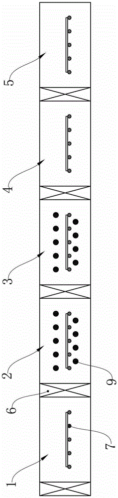
[0049] (1) Fill the loading chamber 1, heating chamber 2, heat preservation chamber 3, cooling chamber 4 and unloading chamber 5 with inert gas nitrogen, the internal air pressure is higher than the external air pressure, and ensure that the loading chamber 1, cooling chamber 4 and unloading chamber 5 The internal air pressure is equal and greater than the heating chamber 2 and the heat preservation chamber 3 with the same pressure as the heating chamber 2;

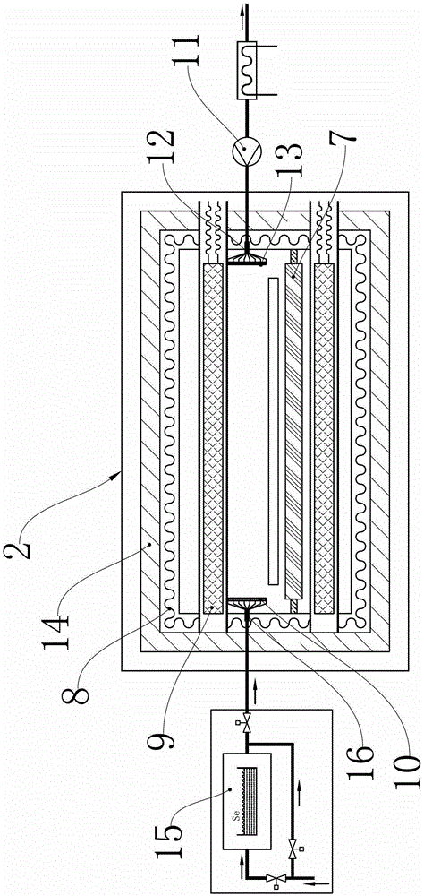
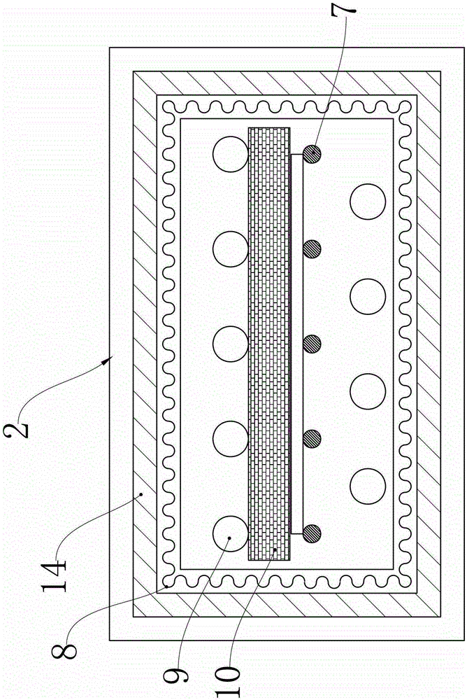
[0050] (2) Preheating the solid selenium vapor of the process gas, using the blast unit and the air extraction unit to realize the forced circulation of the process gas inside the heating chamber 2 and the heat preservation chamber 3, and using the electric heating wire 8 to heat the heat chamber 2 and the heat preservation chamber The temperature of the heat insulation layer 14 of the chamber 3 is 240°C, and the temperature in the chamber ...

Embodiment 2

[0054] The non-vacuum step-by-step fast selenization method comprises the steps:

[0055] (1) Fill the loading chamber 1, heating chamber 2, heat preservation chamber 3, cooling chamber 4 and unloading chamber 5 with inert gas argon, the internal pressure is higher than the external pressure, and ensure that the loading chamber 1, cooling chamber 4 and unloading chamber The air pressure in 5 is equal and greater than that of the heating chamber 2 and the heat preservation chamber 3 with the same pressure as the heating chamber 2;

[0056] (2) Preheat the process gas hydrogen selenide, utilize the blast unit and the air extraction unit to realize the forced circulation of the process gas inside the heating chamber 2 and the heat preservation chamber 3, and use the electric heating wire 8 to heat to the heat preservation chamber 2 and the heat preservation chamber The temperature of the heat insulation layer 14 of the cavity 3 is 250°C, and the temperature in the cavity of the h...

Embodiment 3

[0060] The non-vacuum step-by-step fast selenization method comprises the steps:

[0061] (1) Fill the loading chamber 1, heating chamber 2, heat preservation chamber 3, cooling chamber 4 and unloading chamber 5 with inert gas nitrogen, the internal air pressure is higher than the external air pressure, and ensure that the loading chamber 1, cooling chamber 4 and unloading chamber 5 The internal air pressure is equal and greater than the heating chamber 2 and the heat preservation chamber 3 with the same pressure as the heating chamber 2;

[0062] (2) Preheating the solid selenium vapor of the process gas, using the blast unit and the air extraction unit to realize the forced circulation of the process gas inside the heating chamber 2 and the heat preservation chamber 3, and using the electric heating wire 8 to heat the heat chamber 2 and the heat preservation chamber The temperature of the heat insulation layer 14 of the chamber 3 is 260°C, and the temperature in the chamber ...


PUM


Abstract

The invention discloses a non-vacuum stepping pass-type rapid selenizing device which comprises a process chamber. The process chamber is divided into a loading chamber, a heating chamber, a heat insulation chamber, a cooling chamber and an unloading chamber which are sequentially arranged by latches, the heating chamber and the heat insulation chamber are provided with a heating unit, a blast unit and a gas exhaust unit, the heating unit comprises electric heating wires, an upper row of halogen lamps and a lower row of halogen lamps, the electric heating wires are evenly distributed inside the heating chamber and the heat insulation chamber, and the blast unit and the gas exhaust unit are respectively provided with a grid plate for gridding process gas. Besides, the invention further discloses a selenizing method implemented by the non-vacuum stepping pass-type rapid selenizing device. Uniformity of a gas dispersion flow field, dispersion process temperature and temperature rise are efficiently controlled, and production efficiency can be greatly improved by means of rapid selenizing on the premise of ensuring large-area selenizing uniformity.

Description

technical field [0001] The invention relates to the technical field of solar cell selenization, in particular to a non-vacuum step-through fast selenization device and a selenization method realized by the same. Background technique [0002] At present, the selenization device is one of the important process equipment for doping semiconductors. It diffuses the dopant material into the substrate under high temperature conditions to change and control the type, concentration and distribution of substances in the material. In particular, in the process of preparing copper indium selenium thin film solar cells by selenization after prefabricating the metal layer, the selenization device is the key equipment for the post selenization process and the preparation of high-efficiency absorption layers. [0003] The internationally accepted technical routes for copper indium gallium selenide thin film solar cells are vacuum evaporation method and selenization method after prefabricate...

Claims


Application Information

Patent Timeline
Patent Type & Authority Patents(China)
IPC IPC(8): H01L21/223H01L21/67C23C8/06C30B31/06
Inventor 李和胜李劼闫升运孙琳王岩
Owner 山东孚日光伏科技有限公司
Why Eureka
Try Eureka