Multi-point Flow Velocity Pressure Temperature Integrated Measuring Device
A measuring device, multi-point technology, applied in the direction of measuring device, temperature measurement of moving fluid, pressure difference measurement between multiple valves, etc. The location is difficult to meet and other problems, to achieve the effect of achieving multi-point pressure averaging, reducing operation and maintenance costs, and ensuring accuracy
- Summary
- Abstract
- Description
- Claims
- Application Information
AI Technical Summary
Problems solved by technology
Method used
Image
Examples
Embodiment 1
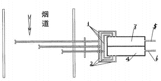
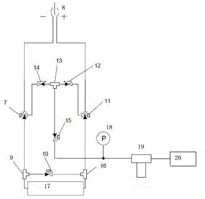
[0033] The multi-point flow rate, pressure and temperature integrated measurement device is composed of a gas path detection unit 8 , a blowback calibration unit and a sensor measurement unit 17 . Such as image 3 and 4 As shown, the gas path detection unit 8 is composed of a porous pitot tube, a mounting flange, and a temperature sensor, and the porous pitot tube is composed of a dynamic pressure tube and a static pressure tube, see image 3 and Figure 4As shown, the dynamic pressure tube 21 is equidistantly provided with 4 concave holes, which can detect the dynamic pressure at different points at the same time. It is a concave hole, facing the direction of flue gas flow, which can eliminate the unevenness of the gas flow direction; the static pressure pipe 22 is located along the flow direction of the flue gas Vs, next to the back of the dynamic pressure pipe 21, and is equally spaced on it. There are 4 sets of static pressure opposite holes, and the two concave holes o...
Embodiment 2
[0043] The material of the porous pitot tube is SS316L, and a more corrosion-resistant anticorrosion layer, such as polytetrafluoroethylene, is sprayed on the outside of the porous pitot tube, and other devices are the same as in embodiment 1.
Embodiment 3
[0045] Such as Figure 5 As shown, the porous pitot tube is composed of a dynamic pressure tube 21 , a static pressure tube 22 , a temperature sensor built-in tube 23 and a heat tracing tube 24 . Among them, the temperature sensor built-in pipe 23 and the heat tracing pipe 24 are respectively located in the concave shape of the two circumscribed circles formed by the dynamic pressure pipe 21 and the static pressure pipe 22, and are close to the dynamic pressure pipe 21 and the static pressure pipe 22; the heat tracing pipe 24 There is a heating material wrapped inside. When the temperature of the smoke is too low, the heating function is activated to prevent the temperature of the smoke from being low. The water in the smoke will appear in the form of water mist and water droplets, which will corrode the Pitot tube. Other devices are with embodiment 1.
PUM
 Abstract
Description
Claims
Application Information
 - R&D
- Intellectual Property
- Life Sciences
- Materials
- Tech Scout
- Unparalleled Data Quality
- Higher Quality Content
- 60% Fewer Hallucinations
Browse by: Latest US Patents, China's latest patents, Technical Efficacy Thesaurus, Application Domain, Technology Topic, Popular Technical Reports.
© 2025 PatSnap. All rights reserved.Legal|Privacy policy|Modern Slavery Act Transparency Statement|Sitemap|About US| Contact US: help@patsnap.com


