Desulfurization device for purifying gas
A desulfurization device and technology for gas purification, which are applied in the fields of gas fuel, combustible gas purification, liquid scrubbing gas purification, etc., can solve the problems of high construction cost and operating energy consumption, achieve the benefits of residence time, improve the gas-liquid mass transfer area, increase the Effect of gas-liquid contact area
- Summary
- Abstract
- Description
- Claims
- Application Information
AI Technical Summary
Problems solved by technology
Method used
Image

Examples
Embodiment 1
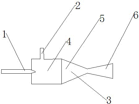
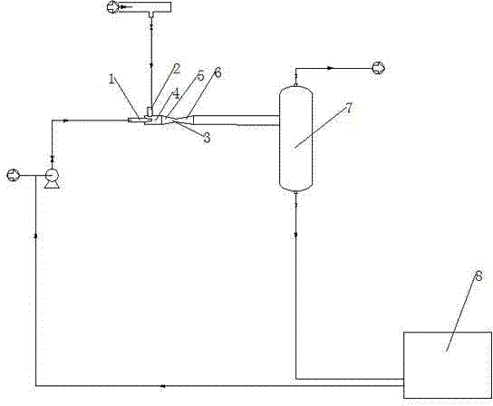
[0037] The desulfurization device described in this embodiment includes: a desulfurizer 3 and a gas-liquid separator 7 .
[0038] Such as figure 1 As shown, the desulfurizer 3 is sequentially provided with a buffer zone 4, a front-end convergence zone 5 and a rear-end diffusion zone 6 along the lateral direction. Nozzle 1, and the atomizing nozzle 1 is set close to the center of the buffer zone 4, and an air outlet is arranged in the rear-end diffusion area 6; in the front-end convergence area 5, the spray nozzle 1 The showering direction is perpendicular to the air intake direction of the air inlet 2; wherein, the buffer zone 4 is a cylinder with a constant diameter, and the front-end convergence zone 5 is a frustum-shaped cylinder that gradually shrinks along the gas flow direction, The contraction ratio of the front-end convergence zone 5 is 1:3; the rear-end diffusion zone 6 is a frustum-shaped cylinder gradually expanding along the gas flow direction, and the expansion r...
Embodiment 2
[0043] The desulfurization device described in this embodiment includes: a desulfurizer 3 and a gas-liquid separator 7 .
[0044] The desulfurizer 3 is sequentially provided with a buffer zone 4, a front convergence zone 5, a middle throat zone 9, and a rear diffusion zone 6 along the transverse direction. An atomizing nozzle 1, and the atomizing nozzle 1 is arranged near the center of the buffer zone 4, and an air outlet is arranged in the rear-end diffusion area 6; in the front-end convergence area 5, the atomizing nozzle 1 The spraying direction is perpendicular to the air intake direction of the air inlet 2; wherein, the buffer zone 4 is a cylinder with a constant diameter; the front end convergence zone 5 is a frustum-shaped cylinder that gradually shrinks along the gas flow direction body, the contraction ratio of the front-end convergence zone 5 is 1:3; the middle throat zone 9 is a cylindrical body with a constant diameter, that is, the diameter of the middle throat zo...
Embodiment 3
[0049] The desulfurization device described in this embodiment includes: a desulfurizer 3 and a gas-liquid separator 7 .
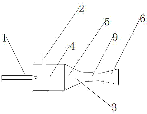
[0050] Such as figure 2 As shown, the desulfurizer 3 is sequentially provided with a buffer zone 4, a front convergence zone 5, a middle throat zone 9, and a rear diffusion zone 6 along the transverse direction. The buffer zone 4 is provided with an air inlet 2 and a The atomizing nozzle 1 of the desulfurization slurry, and the atomizing nozzle 1 is set close to the center of the buffer zone 4, and an air outlet is arranged in the rear-end diffusion area 6; in the front-end convergence area 5, the mist The spraying direction of the nozzle 1 is perpendicular to the air intake direction of the air inlet 2; wherein, the buffer zone 4 is a cylindrical body with a constant diameter; A frustum-shaped cylinder, the shrinkage ratio of the front-end convergence area 5 is 1:5; the middle throat area 9 is a frusto-conical cylinder that gradually shrinks along the g...
PUM
| Property | Measurement | Unit |
|---|---|---|
| Particle size | aaaaa | aaaaa |
| Particle size | aaaaa | aaaaa |
| Particle size | aaaaa | aaaaa |
Abstract
Description
Claims
Application Information
 - R&D
- Intellectual Property
- Life Sciences
- Materials
- Tech Scout
- Unparalleled Data Quality
- Higher Quality Content
- 60% Fewer Hallucinations
Browse by: Latest US Patents, China's latest patents, Technical Efficacy Thesaurus, Application Domain, Technology Topic, Popular Technical Reports.
© 2025 PatSnap. All rights reserved.Legal|Privacy policy|Modern Slavery Act Transparency Statement|Sitemap|About US| Contact US: help@patsnap.com