
Hybrid energy storage system based on ordered energy control

A hybrid energy storage system and monitoring system technology, applied in the field of hybrid energy storage systems, can solve the problems of high price, low cycle times, and low specific energy, so as to improve operational flexibility and controllability, light weight, and occupy small area effect

Active Publication Date: 2013-05-22
STATE GRID CORP OF CHINA +1
View PDF4 Cites 39 Cited by
  • Summary
  • Abstract
  • Description
  • Claims
  • Application Information

AI Technical Summary

Problems solved by technology

Lead-acid battery energy storage system has low mass-to-energy ratio and volumetric energy ratio and fewer cycles, and it is easy to cause certain pollution in the process of mass production or recycling; lithium-ion battery energy storage system has high raw material cost and production process Complexity makes it expensive. In addition, lithium-ion batteries have strict requirements on charge and discharge control and operating environment, and have exploded in the case of overcharge, overdischarge or overtemperature, posing safety hazards; supercapacitor battery energy storage systems Its discharge time is short and its specific energy is low, which cannot meet the requirements of continuous power supply to the grid
Therefore, in order to better meet the grid's requirements for energy storage systems with high capacity, long life, high energy storage and release, smooth pulse charging peaks, and low initial investment costs, it is necessary for the energy storage system to have high specific power and high cycle time. Life and other characteristics, and at the same time can effectively reduce the energy storage system investment cost, floor space, self-weight, etc., but the energy storage system using a single energy storage carrier cannot meet the above requirements

Method used

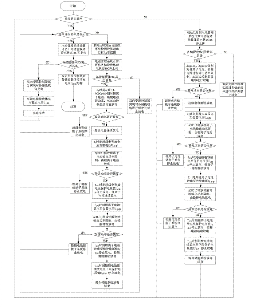

Image

  • Hybrid energy storage system based on ordered energy control
  • Hybrid energy storage system based on ordered energy control

Examples


Embodiment Construction

[0027] The present invention will be further described below in conjunction with the accompanying drawings and embodiments.

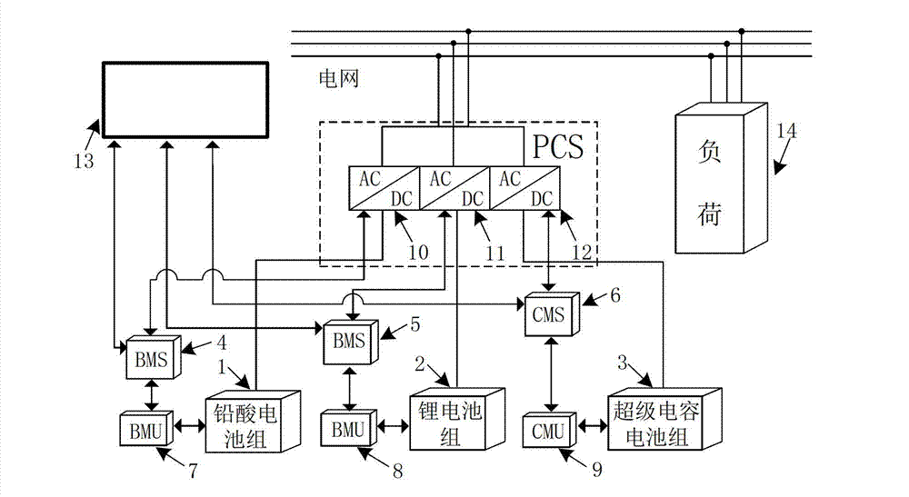
[0028] figure 1 Among them, the energy storage carrier part: lead-acid battery pack 1, lithium battery pack 2 and supercapacitor battery pack 3; among them, lead-acid battery pack 1 and lithium battery pack 2 are used as energy storage batteries, fully combining lead-acid batteries and lithium-ion batteries Advantages and disadvantages, to maximize strengths and avoid weaknesses, so that the two batteries can complement each other in terms of initial investment cost, capacity storage, floor area, service life, and recycling. As a power-type supercapacitor battery pack 3, it has the advantage of continuous high-pulse charge rate discharge of more than 10s, and forms complementary advantages with energy-type lead-acid battery pack 1 and lithium battery pack 2 in terms of energy and rate.

[0029] Two-way conversion control part: adopts unipolar design sc...


PUM


Abstract

The invention relates to a hybrid energy storage system comprising various energy storage carriers. The system is mainly based on an ordered energy control strategy, the energy storage carriers are selectively discharged in a current-limiting or power-limiting mode through a pulse width modulation (PWM) closed-loop control principle and a monitoring system selective control principle, the advantages of the energy storage carriers are combined and complemented, the disadvantages of the energy storage carriers are overcome, and the aim of ordered energy utilization of different energy storage carriers is fulfilled according to a discharge priority sequence, namely a third energy storage subsystem, a second energy storage subsystem and a first energy storage subsystem. By the hybrid energy storage system, the phenomenon that the power of a power grid fluctuates because a wind and light power generation system or a high-power load and the like are connected to the power grid is avoided, smoothing compensation is realized, the quality of electric energy is improved, and the stable operation of the power grid is ensured.

Description

technical field [0001] The invention relates to a power system energy storage system and method, in particular to a hybrid energy storage system based on energy orderly control. Background technique [0002] As the country continues to promote the development of smart grids, micro-grids, renewable energy and electric vehicles, energy storage technology, which is its key technical support, has also achieved rapid development. At present, the common forms of energy storage can be divided into four categories: electrochemical energy storage, physical energy storage, electromagnetic energy storage and phase change energy storage. Among them, energy storage methods such as physical energy storage, electromagnetic energy storage, and phase change energy storage cannot be developed and applied on a large scale due to limitations in technical level, geographical environment, operating conditions, and initial investment costs. However, with the continuous breakthrough of electrochem...

Claims


Application Information

Patent Timeline
IPC IPC(8): H02J3/28
Inventor 孙树敏陈嵩李广磊慕忠君程艳曹同利
Owner STATE GRID CORP OF CHINA
Learn More