Method for producing laminated film

一种制造方法、薄膜的技术,应用在层叠薄膜领域,能够解决透明导电性薄膜白化等问题

Active Publication Date: 2014-06-18
NITTO DENKO CORP
View PDF9 Cites 0 Cited by
  • Summary
  • Abstract
  • Description
  • Claims
  • Application Information

AI Technical Summary

Problems solved by technology

[0008] On the other hand, when a heat-shrinkable transparent resin film such as polyethylene terephthalate is used as the transparent film substrate used for the transparent conductive laminated film, the low-molecular components contained in the transparent film substrate (Oligomer) is precipitated by heating, and there is a problem of whitening of the transparent conductive film

Method used


Image

  • Method for producing laminated film
  • Method for producing laminated film
  • Method for producing laminated film

Examples


Embodiment 1

[0105] (Formation of hard coat layer)

[0106] As a hard coat forming material, it was prepared as follows: Add 5 parts by weight of 1-hydroxy-cyclohexyl-phenyl to 100 parts by weight of acrylic and polyurethane resin (UNIDIC17-806 manufactured by DAINIPPON INK AND CHMICALS INCORPORATED (DIC)) Ketone (IRGACURE184, manufactured by Ciba Specialty Chemicals Co., Ltd.) was diluted with toluene to a concentration of 30% by weight as a photopolymerization initiator.

[0107] The material for forming the hard coat layer was applied as a first transparent resin film on one side of a polyethylene terephthalate film having a thickness of 125 μm, and dried at 90° C. for 3 minutes. Thereafter, use a high-pressure mercury lamp at a cumulative light intensity of 300mJ / cm 2 Under UV irradiation, a hard coat layer with a thickness of 7 µm was formed.

[0108] (Preparation of the first lamination film: Formation of the cured layer)

[0109] Prepare a cured layer forming material containing ...

Embodiment 2

[0117] In the preparation of the first laminated film (formation of the cured layer) in Example 1, except for the use of 2-hydroxy-1-{4-[4-(2-hydroxy-methyl-propionyl)benzyl]phenyl}- 2-Methyl-propan-1-one (IRGACURE127, manufactured by Ciba Specialty Chemicals, 10% thermal weight loss temperature in the thermal weight loss test: 263°C) was used as a photopolymerization initiator, and a second laminated film was obtained in the same manner as in Example 1. . In addition, crystallization treatment was performed in the same manner as in Example 1.

reference example 1

[0121] 1-Hydroxy-cyclohexyl-phenyl ketone (IRGACURE184, manufactured by Ciba Specialty Chemicals, Inc., 10% thermal weight loss temperature in the thermal weight loss test: 154°C) was used in the production of the first laminated film of Example 1 (formation of the cured layer) A second laminated film was obtained in the same manner as in Example 1, except that the drying temperature of the coating layer was changed to 80° C. as the photopolymerization initiator, and heat treatment was performed at 150° C. for 1 minute after ultraviolet irradiation. In addition, crystallization treatment was performed in the same manner as in Example 1.

[0122] The following evaluations were performed on the first laminated film obtained in Examples and Comparative Examples and the second laminated film (transparent conductive laminated film) subjected to the crystallization treatment. The results are shown in Table 1. In addition, Table 1 describes the thermal weight loss of the photoinitia...


PUM

PropertyMeasurementUnit
temperatureaaaaaaaaaa
heat shrinkage ratioaaaaaaaaaa
particle diameteraaaaaaaaaa

Abstract

A process including (1) applying a solution composition to one or both sides of a first transparent resin film to form a coating layer or layers, wherein the solution composition contains an active energy ray-curable compound, a photopolymerization initiator, and a solvent, wherein the photopolymerization initiator has a 10% weight loss temperature of 170° C. or more as measured by a loss-on-heating test; (2) removing, after the coating step (1), a solvent from the coating layer or layers by drying under such temperature conditions that the first laminated film obtained has a thermal shrinkage of 0.5% or less when heated at 150° C. for 1 hour, and (3) curing the coating layer or layers after the heat-treating step (2). A second laminated film produced with the first laminated film makes it possible to suppress curling and to prevent oligomer precipitation.

Description

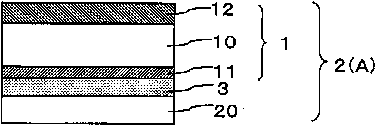
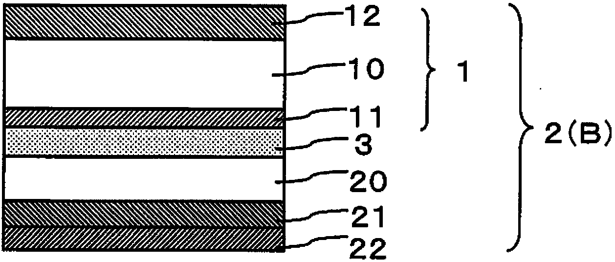
technical field [0001] The present invention relates to a method for producing a laminated film (first laminated film) having a cured layer on one or both surfaces of a heat-shrinkable first transparent resin film. The first laminated film obtained by this production method is used to form a second laminated film by laminating a heat-shrinkable second transparent resin film on the cured layer via an adhesive layer. It can be used in various applications such as optical applications. [0002] For example, when the second transparent resin film has a transparent conductive film, the second laminated film can be used as a laminate of transparent conductive films. The transparent conductive film can be used as a transparent electrode in a display system such as a liquid crystal display or an electroluminescent display, or a touch panel such as an optical system, an ultrasonic system, an electrostatic capacitance system, or a resistive film system. In addition, transparent conduc...

Claims


Application Information

Patent Timeline
Patent Type & Authority Patents(China)
IPC IPC(8): B05D3/02B05D3/06B32B7/02B32B27/16
CPCB32B2255/28B32B2307/202B32B27/36B32B2255/10B32B27/20B32B27/08B32B2255/26B32B38/08B32B7/12B32B37/203B32B2037/243B32B2038/168B32B2309/02B32B2309/04B32B2310/0806B32B2457/20B32B2457/208Y10T156/10B32B37/12B32B37/24B32B2038/0076
Inventor 鹰尾宽行高田胜则中川大五郎小泽博纪
Owner NITTO DENKO CORP
Why Eureka
Try Eureka