Pressurizing heating oil gas mixing transportation system and method

A technology of oil-gas mixed transportation and oil-gas mixed transportation pump, which is applied in the pipeline system, gas/liquid distribution and storage, mechanical equipment, etc. It can solve the problems of increasing the pressure energy loss of the furnace tube, affecting normal production, and reducing the service life. Effects of project investment and operation energy consumption, reduction of total gas-liquid transport volume, and reduction of gas flow

Active Publication Date: 2013-08-14
PETROCHINA CO LTD +2
View PDF6 Cites 16 Cited by
  • Summary
  • Abstract
  • Description
  • Claims
  • Application Information

AI Technical Summary

Problems solved by technology

[0004] 1. Use a container-type fuel gas separator to separate natural gas from the oil-gas mixture and use it as fuel gas for the heating furnace. As a result, the fuel gas separation equipment (fuel gas separator) is bulky and expensive, and has to be installed outdoors. It needs to be installed in winter. Heat trace antifreeze, troublesome operation and management
[0005] 2. The gas-liquid mixture sequentially enters the parallel mixed pump unit through the inlet pump manifold from below or above the mixed pump inlet, which cannot ensure that the inlet gas content of each pump in the parallel pump unit is consistent, resulting in bias flow Phenomenon, so that the pump with a high inlet gas content lacks liquid lubrication and cooling, thermal expansion and wear occur, and the failure rate increases
[0006] For example, the maximum allowable air content rate at the inlet of the twin-screw mixed pump is 95%. When the two pumps are operated in parallel, only when the inlet liquid flow rate and gas flow rate of each pump are completely equal can the inlet air content of the two pumps be made The rate is exactly 95%. If there is a bias flow phenomenon, there must be a pump with an inlet gas content rate greater than 95%, which will lead to overheating and wear of the moving parts such as the screw, increase the failure rate, and reduce the service life, affecting normal production and increasing the cost of the equipment. maintainance fee
[0007] 3. The desand removal effect of the pump filter of the mixed pump is poor, which leads to faster wear of the twin-screw mixed pump and high maintenance costs; the filter is manually disassembled and updated, which does not meet the requirements of SHE
In cold areas, since the mixing pump and its filter are installed indoors, during the operation of cleaning or replacing the filter screen, crude oil will flow to the ground, natural gas will be emitted to the space of the pump room, and the cleaned solid particles will be sticky The attached oil stains cannot be cleaned, causing unavoidable safety and environmental problems
[0011] 4. Adopting the technology that the gas-liquid mixture directly enters the tubular heating furnace through the inlet manifold, resulting in vibration and erosion corrosion caused by gas-liquid impact flow in the heating furnace coil, affecting the safe operation of the heating furnace and reducing its use service life, increasing the pressure energy loss of the furnace tube
[0012] The heating coil in the furnace of the water jacket heating furnace (tube furnace) commonly used in oil fields is composed of a multi-return coil with only one inlet and outlet. Due to the existence of several 180° elbows in the multi-return pipeline in the furnace body, the gas-liquid two-phase Severely turbulent gas-liquid eddies and impact flow patterns are formed in the heating coil, causing coil vibration and erosion corrosion; at the same time, the pressure drop of gas-liquid two-phase flow in the furnace tube is higher than that of gas-liquid single-phase flow. Increased pressure energy loss of heating furnace

Method used


Image

  • Pressurizing heating oil gas mixing transportation system and method
  • Pressurizing heating oil gas mixing transportation system and method
  • Pressurizing heating oil gas mixing transportation system and method

Examples


Embodiment approach 1

[0054] Implementation Mode 1: Oil and gas mixed transportation process suitable for operation of one mixed transportation pump

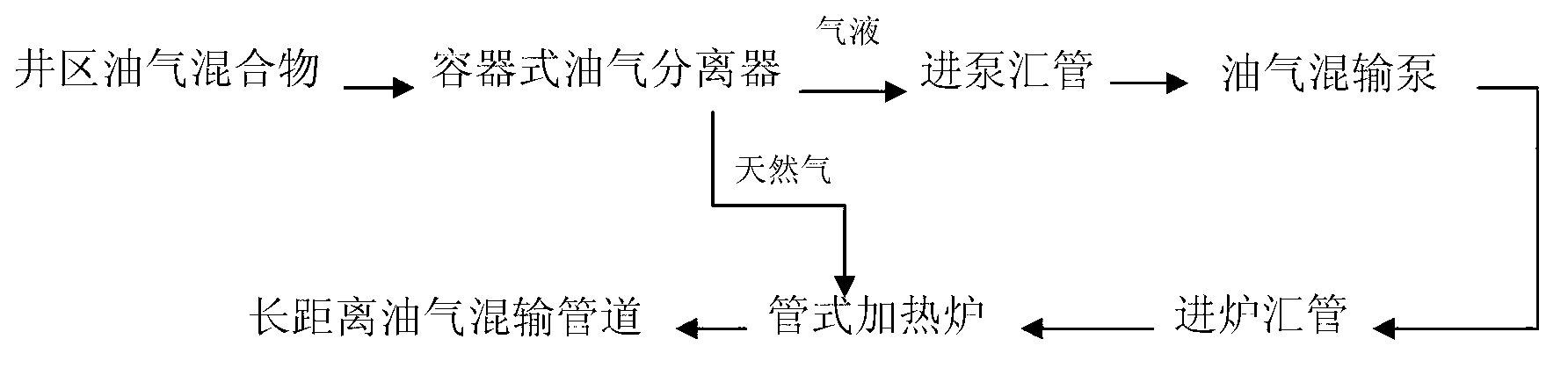
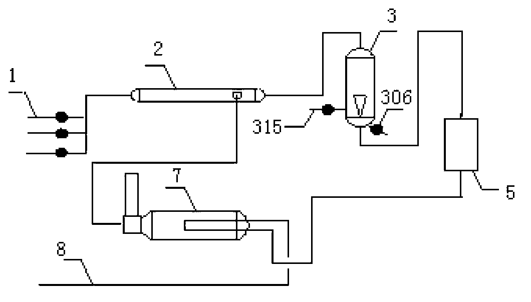
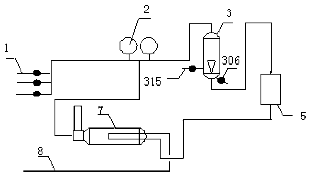
[0055] see figure 2 As shown, a pressurized heating oil-gas mixed transportation system provided by the present invention includes an intake valve group 1, a fuel gas separator 2, a multi-phase vibration desander 3, and an oil-gas mixed transportation pump 5 connected sequentially through pipelines. , a tubular heating furnace 7 and a long-distance oil-gas mixed transportation pipeline 8. The main feature of this system is that on the basis of the existing technology, a new type of multi-phase vibration desander 3 is added between the fuel gas separator 2 and the oil-gas mixing pump 5, and the multi-phase vibration desander 3 The inlet of the fuel gas separator is connected to the gas-liquid outlet of the fuel gas separator 2, and the gas-liquid outlet of the multi-phase vibration desander 3 is connected to the oil-gas mixed delivery pump 5 through...

Embodiment approach 2

[0102] Implementation mode 2: Oil and gas mixed transportation process suitable for parallel operation of more than two mixed transportation pumps

[0103] Another pressurized heating oil-gas mixed transportation system provided by the present invention, see Figure 10 As shown, it includes the intake valve group 1, the fuel gas separator 2, the multi-phase vibration desander 3, the inlet uniform flow device 4 of the multi-phase mixed pump group connected in sequence through the pipeline, and multiple oil and gas mixed transport units connected in parallel. Pump 5, tubular heating furnace 7 and long-distance oil and gas mixed transportation pipeline 8. The main feature of this system is that on the basis of the first embodiment, a multi-phase mixed-transport pump set inlet uniform flow device 4 is added at the inlet of the multi-phase vibration desander 3 and multiple parallel-operated oil-gas mixed transport pumps 5 . The inlet uniform flow device 4 of the multi-phase mixed ...


PUM


Abstract

The invention relates to a pressurizing heating oil gas mixing transportation system and method. The system comprises an in-station valve group, a fuel gas separator, an oil gas mixing transportation pump, a pipe type heating furnace and a long-distance oil gas mixing transportation pipe which are sequentially communicated through a pipe. A multi-phase shock excitation sand remover, a multi-phase mixing transportation pump group inlet uniform flow device and a gas liquid separation flow divider. Gas and liquid mixture from an oil field well area enters the pipe type fuel gas separator, a part of natural gas is separated to serve as fuel of the heating furnace, surplus gas liquid mixture enters the multi-phase shock excitation sand remover to be subjected to sand removing, enters the multi-phase mixing transportation pump group inlet uniform flow device to be subjected to uniform flow distribution and is delivered to the gas liquid separation flow divider through the oil gas mixing transportation pump, and the separated liquid enters the pipe type heating furnace to be heated and is mixed with the separated gas to enter the long-distance oil gas mixing transportation pipe. Safe stable high-efficiency operation of the system is guaranteed, service life of devices is prolonged, and project investment, energy consumption, operation maintenance and operation cost are reduced.

Description

technical field [0001] The invention belongs to the technical field of oil exploitation ground engineering, and in particular relates to a system and a method for pressurizing and heating oil and gas mixed transportation in an oil field. Background technique [0002] At present, in the oil and gas gathering and transportation system of oil field surface engineering, more and more pressurized heating oil and gas mixed transportation technology is used. The system and process are as follows: figure 1 As shown, after the oil-gas mixture in the well area is separated by the container-type fuel-gas separator, the gas-liquid enters the mixing pump through the pump inlet manifold, and the oil-gas mixture output by the mixing pump enters the tubular heating furnace through the furnace inlet manifold for heating, and then Enter the long-distance oil and gas mixed pipeline; and part of the natural gas separated from the fuel gas separator is introduced into the heating furnace as fuel...

Claims


Application Information

Patent Timeline
Patent Type & Authority Applications(China)
IPC IPC(8): F17D1/02F17D1/14F17D3/03
Inventor 宋承毅李晓红杨峰王延辉闫善超于青春
Owner PETROCHINA CO LTD
Why Eureka
Try Eureka