

Denitration catalyst and preparation method thereof
A denitration catalyst and catalyst technology, applied in the field of denitration catalysts, can solve the problems of ignoring sulfur oxides, decreasing thermal efficiency, clogging catalysts, etc., and achieve the effects of wide active temperature window, low conversion rate, and reduced adsorption and oxidation
- Summary
- Abstract
- Description
- Claims
- Application Information
AI Technical Summary
Problems solved by technology
Method used
Image

Examples
Embodiment 1
[0035] Embodiment 1: the preparation of composite catalyst
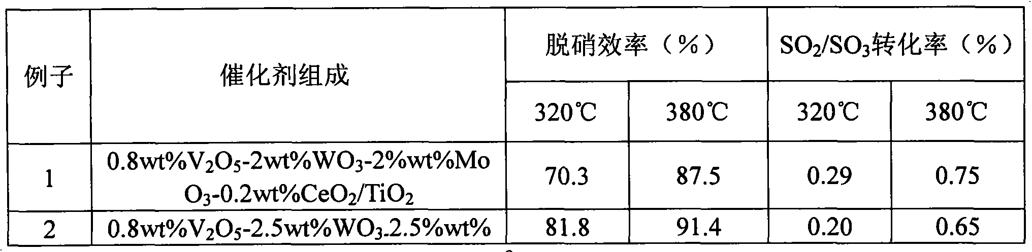
[0036] (0.8wt%V 2 O 5 -2wt% WO 3 -2wt%MoO 3 -0.2wt%CeO 2 / TiO 2 )
[0037] a) First heat 2.85kg of ionized water to 85°C, add 0.146kg of monoethanolamine and stir to dissolve, then add 0.328kg of ammonium tungstate, 0.612kg of ammonium molybdate and 0.163kg of ammonium metavanadate and stir to dissolve to make a light yellow solution .
[0038] b) 0.076 kg of cerium nitrate was dissolved in 0.060 kg of monoethanolamine solution to form a transparent solution, and then gradually added to the solution of the above step a to make a flocculent suspension.
[0039] c) Then slowly add 9.75 kg of anatase-type fine-grained titanium dioxide powder to the suspension in step b and stir while adding to make a viscous white thick slurry.
[0040] d) Add 1.95 kg of auxiliary materials and 1.8 kg of molding agent to the viscous white thick slurry obtained in step c and stir to obtain the prepared mixed...
Embodiment 2
[0045] Embodiment 2: the preparation of composite catalyst
[0046] (0.8wt%V 2 O 5 -2.5wt% WO 3 -2.5wt%MoO 3 -0.5wt%CeO 2 / TiO 2 )
[0047] a). First, heat 2.85kg of ionized water to 85°C, add 0.313kg of monoethanolamine and stir to dissolve, then add 0.36kg of ammonium tungstate, 0.765kg of ammonium molybdate and 0.163kg of ammonium metavanadate and stir to dissolve to make light yellow solution.
[0048] b). Dissolve 0.19 kg of cerium nitrate in 0.15 kg of monoethanolamine solution to form a transparent solution, then gradually add the solution in step a above to make a flocculent suspension.
[0049] c). Then slowly add 9.75 kg of anatase-type fine-grained titanium dioxide powder to the suspension in step b and stir while adding to make a viscous white thick slurry.
[0050] d). Add 1.95 kg of auxiliary materials and 1.8 kg of molding agent to the viscous white thick slurry obtained in step c and stir to obtain the prepared mixed material.
[...
Embodiment 3
[0055] Embodiment 3: the preparation of composite catalyst
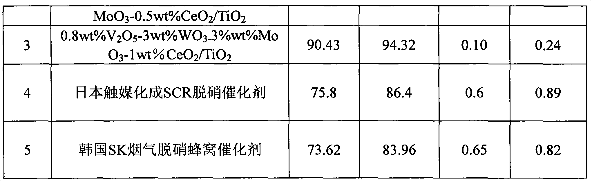
[0056] (0.8wt%V 2 O 5 -3wt% WO 3 -3%wt%MoO 3 -1wt%CeO 2 / TiO 2 )
[0057] a). First heat 2.85kg of ionized water to 85°C, add 0.376kg of monoethanolamine and stir to dissolve, then add 0.492kg of ammonium tungstate, 0.918kg of ammonium molybdate and 0.163kg of ammonium metavanadate and stir to dissolve to make a light yellow solution.
[0058] b). Dissolve 0.38 kg of cerium nitrate in 0.30 kg of monoethanolamine solution to form a transparent solution, then gradually add the solution of the above step a to make a flocculent suspension.
[0059] c). Then slowly add 9.75 kg of anatase-type fine-grained titanium dioxide powder to the suspension in step b and stir while adding to make a viscous white thick slurry.
[0060] d). Then add 1.95kg of auxiliary materials and 1.8kg of molding agent to the viscous white thick slurry obtained in step c, and stir and mix to obtain the prepared mixed ...
PUM
 Abstract
Description
Claims
Application Information