
Method for removing aerosol in ammonia washing desulphurization of flue gas

An aerosol and flue gas technology, applied in separation methods, chemical instruments and methods, and separation of dispersed particles, can solve problems such as aerosol emissions, and achieve the effects of reducing corrosion, improving the ecological environment, and improving the living environment

Inactive Publication Date: 2013-08-28
SHAANXI KEYUAN ENVIRONMENTAL PROTECTION & ENERGY SAVING TECH
View PDF4 Cites 7 Cited by
  • Summary
  • Abstract
  • Description
  • Claims
  • Application Information

AI Technical Summary

Problems solved by technology

At present, all flue gas ammonia scrubbing and desulfurization systems have the problem of aerosol emissions

Method used


Image

  • Method for removing aerosol in ammonia washing desulphurization of flue gas
  • Method for removing aerosol in ammonia washing desulphurization of flue gas

Examples


Embodiment 1

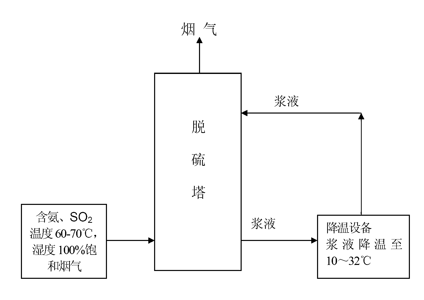
[0011] Process flow chart of the present invention is attached figure 1 , the technical process of the present invention is as follows:

[0012] The spray slurry in the desulfurization section of the desulfurization tower entrains ammonia and SO at the same time as the gas-liquid ratio of 1:3-15 cubic meters per liter and the temperature of 60--70°C and humidity of 100% from the previous process. 2 The saturated flue gas is contacted in countercurrent, heat exchange and chemical reaction are realized simultaneously during the contact process, the temperature of the slurry rises by 5-16°C, and the temperature of the flue gas decreases at the same time. After the slurry falls into the bottom of the desulfurization tower, it is pumped from the bottom into the cooling tower where the slurry is cooled by using the residual pressure. The slurry exchanges heat with the natural air, so that the temperature of the slurry is reduced to a range close to the outdoor air temperature ± 3 °C...

Embodiment 2

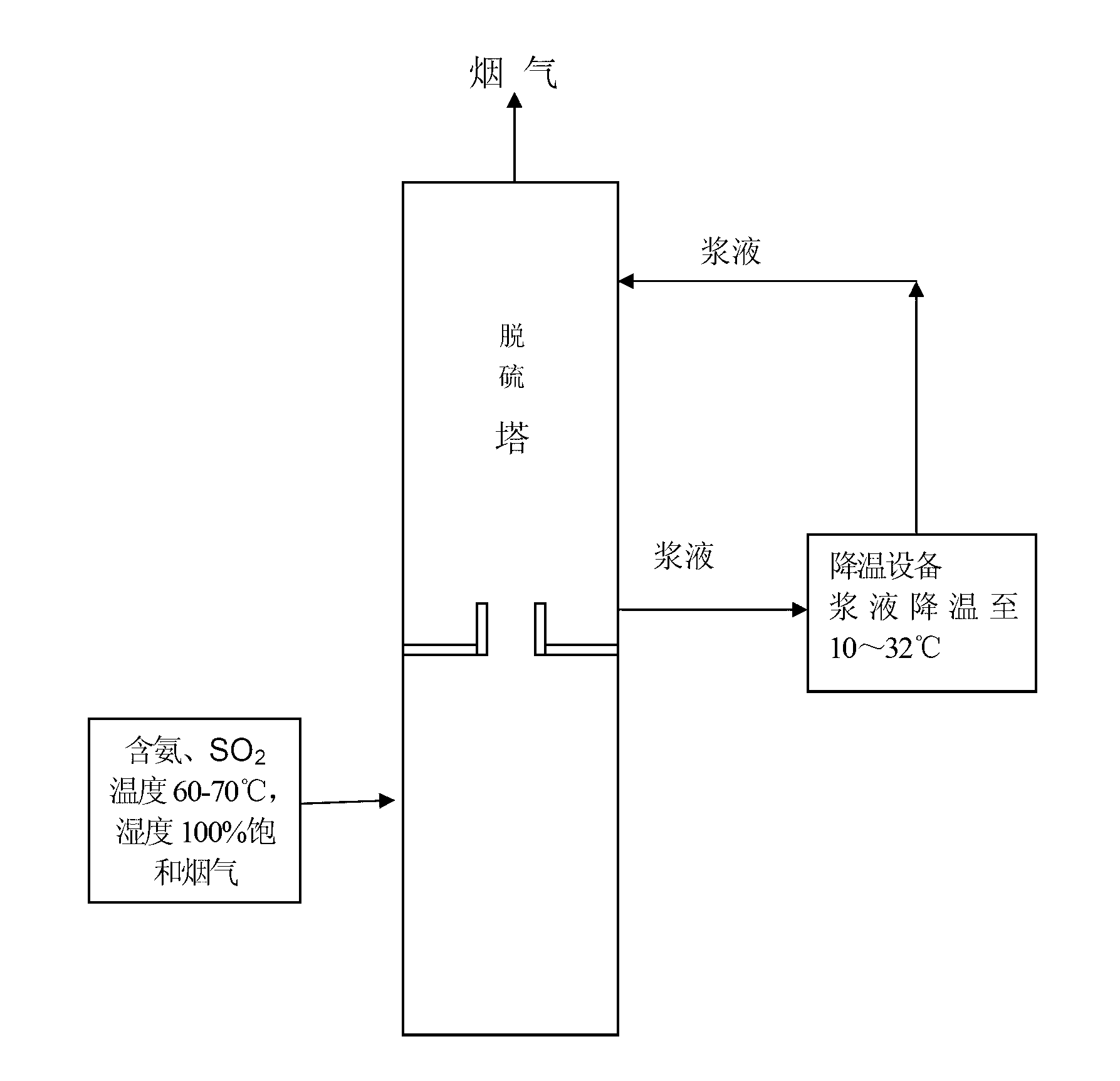
[0014] Process flow of the present invention is attached figure 2 , the technical process of the present invention is as follows:

[0015] In the washing section of the desulfurization tower, the spray slurry is mixed with a gas-liquid ratio of 1:3-15 cubic meters per liter and a temperature of 60--70°C, a humidity of 100%, entrained ammonia, SO 2 The saturated flue gas is contacted in countercurrent, and heat exchange and chemical reaction are realized during the contact process. After the slurry falls into the bottom of the washing section, it is driven from the bottom into a cooling tower for cooling the slurry with a pump or residual pressure. The slurry exchanges heat with the natural air, so that the temperature of the slurry is reduced to a range close to the outdoor air temperature ± 3°C. The temperature is 10-32°C, and then the lift pump is used to drive the spray nozzle into the tower to contact with the flue gas countercurrently to reduce the temperature of the fl...


PUM


Abstract

The invention relates to a method for removing aerosol smog in ammonia desulphurization of flue gas. The method comprises the following steps of: pumping pulp at the bottom part in a desulfurizing tower into a pulp cooling device through a pump or excess pressure, performing heat exchange cooling on the pulp to reduce the temperature of the pulp to 10-32 DEG C, and then, and pumping the pulp into a spray head at the top of the desulfurizing tower through a lifting pump to spray the pulp, wherein the low temperature pulp touches the flue gas in countercurrent to exchange heat so as to reduce the temperature of the flue gas and ensure that all or a part of segments in the desulfurizing tower are at a low temperature operation state of 20-40 DEG C. The method provided by the invention is used for cooling the pulp in a desulfurizing or washing process to make the temperature of the pulp in the desulfurizing tower be close to the atmospheric temperature so as to perfect the operation environment in the desulfurizing tower when SO2 in the desulfurizing tower is absorbed, therefore not only is the ammonium sulfite decomposition is reduced, and the water vapor in the gas phase is condensed, and the ammonia, water and SO2 react to generate ammonium sulfite granules to be absorbed by the pulp to reduce the aerosol in the flue gas, and thus the generation and emission of aerosol in a desulfurization process are eliminated or reduced.

Description

technical field [0001] The invention belongs to the field of atmospheric prevention and environmental protection. For many industries such as thermal power generation, metal smelting, chemical industry, light industry, garbage incineration, etc., it is especially involved in the method of eliminating aerosols in the process of flue gas ammonia scrubbing and desulfurization. Background technique [0002] In the process of flue gas ammonia scrubbing and desulfurization, the slurry containing ammonium sulfite in the desulfurization tower and the SO in the flue gas 2 Countercurrent contact, ammonium sulfite absorbs SO 2 The reaction produces ammonium bisulfite and falls to the bottom of the tower. The desulfurization slurry at the bottom of the tower, a part of the slurry is pumped into the flue gas pre-washing tower in front of the desulfurization tower, and is in countercurrent contact with the high-temperature hot flue gas, concentrated, evaporated and crystallized to produ...

Claims


Application Information

Patent Timeline
IPC IPC(8): B01D53/80B01D53/50B01D53/96
Inventor 史永军史秦博苑
Owner SHAANXI KEYUAN ENVIRONMENTAL PROTECTION & ENERGY SAVING TECH
Learn More