Waveguide Direct Feed Microwave Plasma Torch Device

A microwave plasma and direct-feed technology, applied in the field of chemical measurement, can solve problems such as the limitation of coaxial cable bearing capacity, achieve the effect of improving microwave coupling efficiency and simplifying the complexity

Active Publication Date: 2016-01-06
ZHEJIANG UNIV
View PDF9 Cites 1 Cited by
  • Summary
  • Abstract
  • Description
  • Claims
  • Application Information

AI Technical Summary

Problems solved by technology

[0003] MPT torches usually work with a variety of working gases (argon, helium, nitrogen, air, etc.) in the range of 10-500W, but at high power (>500W) coaxial cables are limited

Method used


Image

  • Waveguide Direct Feed Microwave Plasma Torch Device
  • Waveguide Direct Feed Microwave Plasma Torch Device
  • Waveguide Direct Feed Microwave Plasma Torch Device

Examples


Embodiment 1

[0047] see figure 1 , a waveguide direct-fed microwave plasma torch device, the device is mainly composed of a waveguide part, a tuning and auxiliary part, and a coaxial torch tube part.

[0048] see figure 2 , a schematic side-view profile of the main part of the waveguide direct-fed microwave plasma torch, where

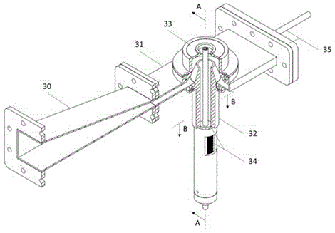
[0049] The waveguide part includes a tapered waveguide 30 and a narrow-side compression waveguide 31, wherein the narrow-side compression waveguide 31 and the matched MPT three-tube coaxial torch 32 constitute the main part of the waveguide direct-fed MPT, and the narrow-side compression waveguide 31 is Microwaves are fed into the main body waveguide.

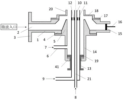
[0050] see image 3 , The coaxial torch 32 part includes the outer tube 14, the middle tube 11, the inner tube 10, the adjusting stud 13 and the coaxial centering washer 12, and the three tubes are in a coaxial structure. The inner diameter of the outer tube 14 is preferably 20-28 mm, the outer diameter of the...

Embodiment 2

[0068] see Figure 6 , Figure 7 , a simulation of electromagnetic field distribution in a waveguide-fed microwave plasma torch device. The simulation results are helpful to understand the working mechanism of this structure. The structure and dimensions of the device used are as described in Example 1.

[0069] Figure 6 It is the electromagnetic field distribution simulation diagram of the waveguide part in this example, and the simulated microwave frequency is 2450MHz. The three sections of waveguides are BJ26, tapered waveguide 30 and narrow-side compressed waveguide 31 respectively. Microwaves are introduced from the left side of the BJ26 waveguide, transmitted to the short-circuit end on the right side of the narrow-side compression waveguide 31 and reflected back, thereby forming a standing wave field inside the waveguide. It can be seen from the figure that the electric field strength gradually becomes stronger from left to right, and is coupled into the torch tub...

Embodiment 3

[0072] Figure 8 It is a diagram of the actual working state of the waveguide direct-fed MPT device designed based on the present invention. The structure and dimensions of the device used are as described in Example 1. The experimental conditions are as follows:

[0073] A magnetron is used as a microwave transmitting device, the output power is continuously adjustable from 100W to 1500W, and the device works at a power of 1000W. The carrier gas and maintenance gas fed into the middle tube 11 and the inner tube 10 are both argon with a purity of 99.999% and a gas flow >1.2 L / min. Oxygen shielding gas is passed between the outer tube 14 and the middle tube 11 to shield the air in the environment, the purity is 99.999%, and the air flow is 1.5L / min. The formed argon plasma flame 36 is as Figure 8 shown.

[0074] Figure 9 Schematic diagram of the structure of the argon plasma flame 36 formed by the waveguide direct-fed microwave plasma torch. The formed plasma contains ...


PUM


Abstract

The invention provides a waveguide direct-feed microwave plasma torch device, which is composed of a waveguide part, a tuning and auxiliary part, and a coaxial torch part. The waveguide part includes a gradient waveguide and a narrow-side compression waveguide; Tube, middle tube, inner tube, adjusting stud and coaxial centering washer; tuning and auxiliary parts include waveguide short-circuit sliding end, torch reflection tuning end and torch upper adjustment end, wherein the waveguide short-circuit sliding end is composed of waveguide short-circuit board Composed of sliding rods, the torch reflection tuning end includes adjustment studs and reflection plates. In the invention, microwave energy is directly fed into the metal coaxial torch through the tapered waveguide and the narrow-side waveguide, and the formed plasma has a central channel, which facilitates the introduction of samples and enhances the tolerance to samples. The device eliminates coaxial cables, coupling rings, etc., improves coupling efficiency, and expands the power of the torch tube. It can be used as an ionization source for atomizers and atomic mass spectrometers, or for the decomposition and treatment of harmful compounds and garbage.

Description

Technical field [0001] The invention is a chemical measurement technology field, involving a waveguide direct feedback microwave plasma torch device. It is a device that uses microwaves and maintains plasma.The atomic mass spectrometry) The atoms or sources required can also be used for the decomposition and treatment of harmful compounds. Background technique [0002] Microwave plasma torch (MPT) was invented by Professor Jin Qinhan in 1985, and the corresponding application patent number was CN94205428.8.The torch tube is a three -metal pipe coaxial structure open at one end. Microwaves can enter the torch tube by conducting / capacitive coupling through coaxial cables.Plasma formed at the end of the torch. [0003] The MPT torch tube is usually worked in a variety of working gases (radon, gaseous, nitrogen, air, etc.) in a range of 10-500W, but the tolerance of coaxial cables (> 500W) of coaxial cables is limited. [0004] This patent directly combines the waveguide structure...

Claims


Application Information

Patent Timeline
Patent Type & Authority Patents(China)
IPC IPC(8): H05H1/46
Inventor 金钦汉于丙文金伟周建光朱旦
Owner ZHEJIANG UNIV
Why Eureka
Try Eureka