
Method for producing junction field effect transistor

A field-effect transistor and manufacturing method technology, which is applied to the manufacture of semiconductor/solid-state devices, electrical components, circuits, etc. The effect of illuminating the effect ability and reducing the additional cost

Inactive Publication Date: 2013-09-04
UNIV OF ELECTRONICS SCI & TECH OF CHINA +1
View PDF3 Cites 7 Cited by
  • Summary
  • Abstract
  • Description
  • Claims
  • Application Information

AI Technical Summary

Problems solved by technology

[0007] In the manufacturing process of traditional junction field effect transistors, since the gate-source isolation oxide layer is used as a masking layer for the diffusion process, many impurities and defects will be introduced into the isolation oxide layer during the manufacturing process, which will reduce the anti-total dose of junction field effect transistors. Radiation effect capability

Method used


Image

  • Method for producing junction field effect transistor
  • Method for producing junction field effect transistor
  • Method for producing junction field effect transistor

Examples


Embodiment Construction

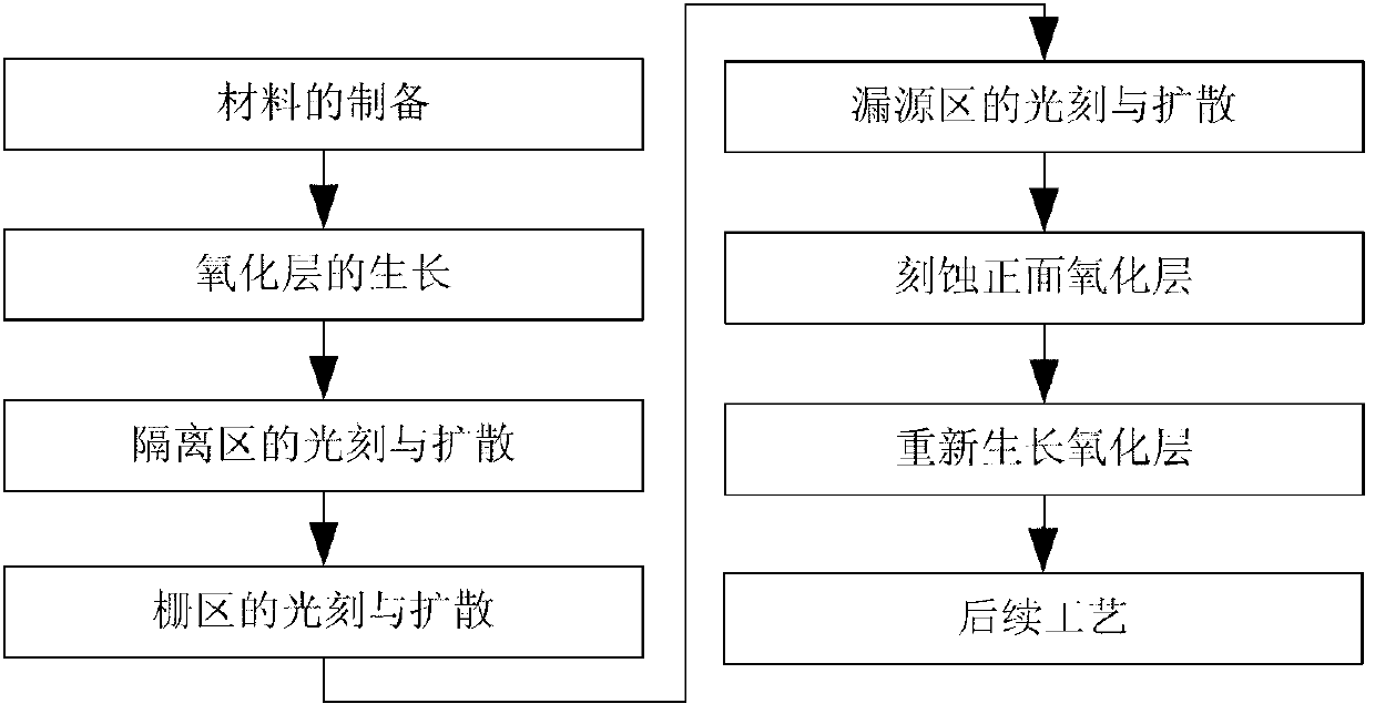
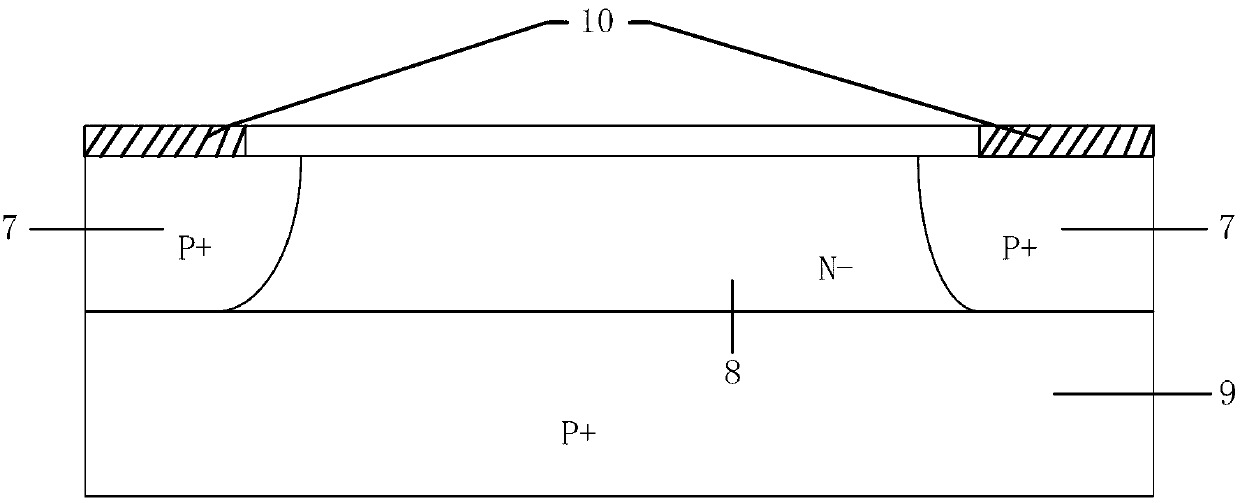
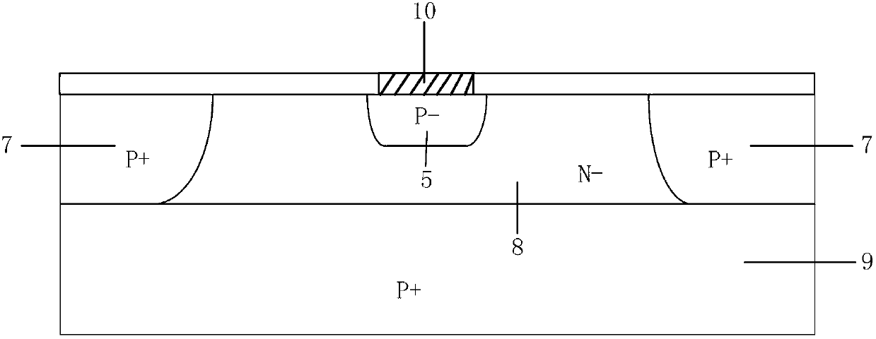
[0028] Now take a kind of N-channel junction field effect transistor with isolation region (its structure diagram is as follows Figure 6 Shown) as an example to describe the proposed method of manufacturing a junction field effect transistor, the specific process is as follows: 400 ~ 450um P + Type substrate and 4 ~ 6um N — Preparation of layer material, growth of oxide layer, photolithography of isolation area, pre-deposition of boron diffusion in isolation area, redistribution and secondary oxidation of boron diffusion in isolation area (corresponding structure diagram as figure 2 shown), photolithography of the gate area, pre-deposition of boron diffusion in the gate area, redistribution and secondary oxidation of boron diffusion in the gate area (the corresponding structure diagram is shown in image 3 shown), photolithography of the drain-source region, pre-deposition of phosphorus diffusion in the drain-source region, redistribution and secondary oxidation of phosphor...


PUM


Abstract

The invention discloses a method for producing a junction field effect transistor, which belongs to the field of semiconductor devices. According to a conventional method for producing the junction field effect transistor, a gate source isolation oxidation layer serves as a masking layer of a diffusion technology, and a large number of impurities and defects can be introduced into the isolation oxidation layer in a production process, so that the total dose irradiation effect resisting capability of the junction field effect transistor can be reduced. The method for producing the junction field effect transistor provided by the invention comprises steps of: before contact hole etching, adopting hydrofluoric acid to completely etch the original oxidation layer, then regrowing the oxidation layer so as to guarantee that denser high-quality oxidation layer having less defects is regrown, and accordingly, improving the total dose irradiation effect resisting capability of the junction field effect transistor. In addition, a masking plate does not need to be added, and moreover, the hydrofluoric acid is utilized to etch the entire oxidation layer of the front side before the contact hole etching and the new high-quality oxidation layer is regrown, so that the method is simple and practicable, and the additional costs brought by adding new processing steps are lowered.

Description

technical field [0001] The invention belongs to the technical field of semiconductor devices and relates to a manufacturing process of semiconductor devices. Background technique [0002] Junction Field Effect Transistor is a multi-subconduction field effect that changes the width of the PN junction depletion layer in the gate region through the gate voltage to modulate the cross-sectional area of ​​the conduction channel, thereby effectively controlling the channel current. Semiconductor device. The Junction Field Effect Transistor was proposed by W.B.Shockley in 1952 to avoid the influence of the surface state and use the PN junction as the gate's internal conductive channel structure. After the development of G.C.Dacey and I.M.Ross, it became the first to reach the practical level. field effect transistor. [0003] Junction field effect transistor is an in-body conductive device that relies on majority carriers to work, which makes it have many advantages: no minority c...

Claims


Application Information

Patent Timeline
IPC IPC(8): H01L21/337
Inventor 李泽宏宋文龙邹有彪宋洵奕吴明进张金平任敏
Owner UNIV OF ELECTRONICS SCI & TECH OF CHINA
Learn More