C/SiC coating with pore structure and preparation method thereof
A technology of pore structure and coating, applied in the field of C/SiC coating containing pore structure and its preparation
- Summary
- Abstract
- Description
- Claims
- Application Information
AI Technical Summary
Problems solved by technology
Method used
Image
Examples
Embodiment 1
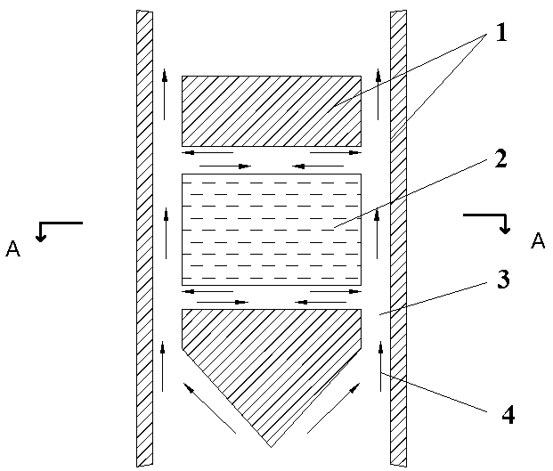
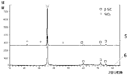
[0032] Example 1: see figure 1 , figure 2 and Figure 10 . The temperature in the constant temperature zone of the deposition chamber in the thermal furnace is 1150°C, the pressure in the furnace is 1kpa, MTS and H 2 The purity of the gas is ≥99%; the flow rate of MTS is determined by the carrier gas H 2 flow control, H 2 The flow rate is 0.3L / min; while diluting gas H 2 The flow rate is 0.6L / min, and the slit width of the "slit-type" deposition chamber is designed to be 2mm. "Slit" deposition chamber see figure 1 and Figure 10 , C / SiC coating phase composition see figure 2 , C / SiC coating surface morphology of C / C composite materials and graphite materials, see respectively image 3 and 4 .
Embodiment 2
[0033] Example 2: see figure 1 , figure 2 and Figure 10 . The temperature in the constant temperature zone of the deposition chamber in the thermal furnace is 1300°C, the pressure in the furnace is 5kpa, MTS and H 2The purity of the gas is ≥99%; the flow rate of MTS is determined by the carrier gas H 2 flow control, H 2 The flow rate is 0.3L / min; while diluting gas H 2 The flow rate is 0.6L / min, and the slit width of the "slit-type" deposition chamber is designed to be 5mm. "Slit" deposition chamber see figure 1 and Figure 10 , C / SiC coating phase composition see figure 2 , C / SiC coating surface morphology of C / C composite materials and graphite materials, see respectively image 3 and 4 .
Embodiment 3
[0034] Embodiment 3: see figure 1 , figure 2 and Figure 10 . The temperature in the constant temperature zone of the deposition chamber in the thermal furnace is 1200°C, the pressure in the furnace is 10kpa, MTS and H 2 The purity of the gas is ≥99%; the flow rate of MTS is determined by the carrier gas H 2 flow control, H 2 The flow rate is 0.4L / min; while diluting gas H 2 The flow rate is 0.9L / min, and the slit width of the "slit-type" deposition chamber is designed to be 8mm. "Slit" deposition chamber see figure 1 and Figure 10 , C / SiC coating phase composition see figure 2 , C / SiC coating surface morphology of C / C composite materials and graphite materials, see respectively image 3 and 4 .
PUM
| Property | Measurement | Unit |
|---|---|---|
| thickness | aaaaa | aaaaa |
Abstract
Description
Claims
Application Information
 - R&D
- Intellectual Property
- Life Sciences
- Materials
- Tech Scout
- Unparalleled Data Quality
- Higher Quality Content
- 60% Fewer Hallucinations
Browse by: Latest US Patents, China's latest patents, Technical Efficacy Thesaurus, Application Domain, Technology Topic, Popular Technical Reports.
© 2025 PatSnap. All rights reserved.Legal|Privacy policy|Modern Slavery Act Transparency Statement|Sitemap|About US| Contact US: help@patsnap.com


