Coated antenna for microwave reader-writer of ETC (electronic toll collection) system

An electronic non-stop and charging system technology, applied in the field of antennas, can solve the problems of high side lobe level, lane interference, main lobe beam width, etc., and achieve the effect of solving adjacent channel interference, sharpening the beam, and improving the gain.

Inactive Publication Date: 2013-10-16
XIDIAN UNIV
View PDF2 Cites 19 Cited by
  • Summary
  • Abstract
  • Description
  • Claims
  • Application Information

AI Technical Summary

Problems solved by technology

However, the use of microstrip arrays not only requires the design of a complex feed network, but also has a wider main lobe beam and a higher side lobe level, which is likely to cause leading interference problems

Method used


Image

  • Coated antenna for microwave reader-writer of ETC (electronic toll collection) system
  • Coated antenna for microwave reader-writer of ETC (electronic toll collection) system
  • Coated antenna for microwave reader-writer of ETC (electronic toll collection) system

Examples


Embodiment 1

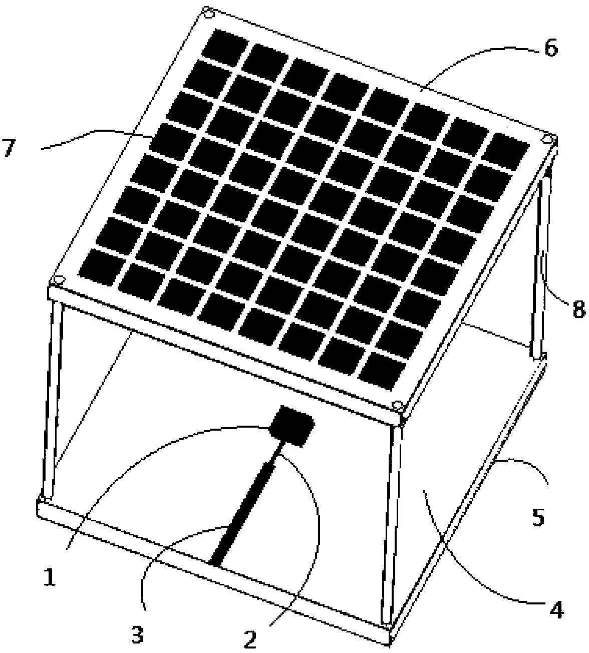
[0027] refer to figure 1 , the present invention is used for the cladding antenna of microwave reader-writer of electronic non-parking toll collection system comprising: circularly polarized radiation patch 1, impedance transformation line 2, 50 ohm microstrip feeder line 3, dielectric substrate 4, ground plate 5 and frequency selection Surface cladding 6, square metal units 7 uniformly arranged two-dimensionally and periodically. The circularly polarized radiation patch 1 is placed in the center of the dielectric substrate 4 and connected to the 50-ohm microstrip feeder 3 through the impedance transformation line 2 to achieve impedance matching. The frequency selective surface coating 6 is fixed directly above the circularly polarized radiation patch 1 through an insulating support 8 and aligned with the four corners of the dielectric substrate 4 .

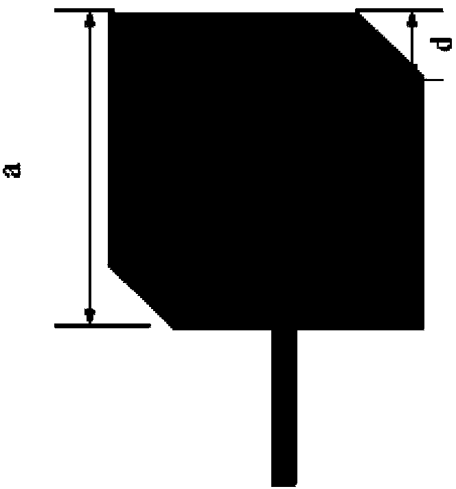
[0028] The approximate value of the side length a of the circularly polarized radiation patch 1 can be determined by the follo...

Embodiment 2

[0044] see figure 1 , this embodiment includes: a circularly polarized radiation patch 1, an impedance transformation line 2, a 50-ohm microstrip feeder 3, a dielectric substrate 4, a ground plate 5, and a frequency-selective surface coating 6, and a uniform two-dimensional periodic arrangement of square metal units 7. The circularly polarized radiation patch 1 is placed in the center of the dielectric substrate 4 and connected to the 50-ohm microstrip feeder 3 through the impedance transformation line 2 to achieve impedance matching. The frequency selective surface coating 6 is fixed directly above the circularly polarized radiation patch 1 through an insulating support 8 and aligned with the four corners of the dielectric substrate 4 .

[0045] The structure of this embodiment is the same as that of Embodiment 1, but the parameters are different. The side length a of the circularly polarized radiation patch 1 is 15.4 mm, the cut-off side length d is 3 mm, the side length b...

Embodiment 3

[0047] see figure 1 , this embodiment includes: a circularly polarized radiation patch 1, an impedance transformation line 2, a 50-ohm microstrip feeder 3, a dielectric substrate 4, a ground plate 5, and a frequency-selective surface coating 6, and a uniform two-dimensional periodic arrangement of square metal units 7. The circularly polarized radiation patch 1 is placed in the center of the dielectric substrate 4 and connected to the 50-ohm microstrip feeder 3 through the impedance transformation line 2 to achieve impedance matching. The frequency selective surface coating 6 is fixed directly above the circularly polarized radiation patch 1 through an insulating support 8 and aligned with the four corners of the dielectric substrate 4 .

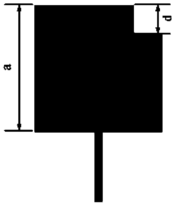
[0048] see image 3 In this embodiment, the circularly polarized radiation patch 1 realizes circular polarization by cutting off a square corner, and the size of the cut off square corner is 1.8 mm. The rest of the structure is the same a...


PUM


Abstract

The invention discloses an antenna for a microwave reader-writer of an ETC (electronic toll collection) system. The antenna comprises a circular polarization radiation paster (1), an impedance transformation line (2), a 50-ohm microstrip feeder line (3), a dielectric substrate (4), a grounding plate (5) and a frequency selection surface coating (6). The circular polarization radiation paster (1) is arranged at the center of an upper surface of the dielectric substrate (4) through etching. The impedance transformation line (2) connects the circular polarization radiation paster (1) with the 50-ohm microstrip feeder line (3). The grounding plate (5) is arranged below a lower surface of the dielectric substrate (4) through etching. The frequency selection surface coating (6) is fixed right above the circular polarization radiation paster (1) through an insulating support (8). Square metal units (7) are arranged below a lower surface of the frequency selection surface coating (6) through etching, and are disposed in two-dimensional periodic arrangement. The coated antenna prevents adjacent channel interference, has the advantages of simple feed network, narrow wave beam, high gain and low side-lobe, and can be expanded to other radio frequency identification systems.

Description

technical field [0001] The invention belongs to the technical field of antennas, in particular to a cladding antenna which can be used in an electronic non-stop toll collection system on expressways. Background technique [0002] The ETC system is an advanced system composed of high-tech equipment and software such as wireless communication technology, automatic identification technology, image processing technology, and computer network technology, so as to realize automatic collection of road tolls without parking. [0003] The ETC system consists of roadside reading and writing equipment RSU, on-board unit OBU, ground sense coil, automatic barrier machine, vehicle detector, fee display, audit system and other parts. The ETC system communicates and exchanges information with the on-board unit through the roadside unit to achieve automatic identification of the vehicle, and automatically deducts the toll from the user's special account, thereby realizing an automatic toll c...

Claims


Application Information

Patent Timeline
Patent Type & Authority Applications(China)
IPC IPC(8): H01Q1/38H01Q1/52
Inventor 李龙赵宇毛建军
Owner XIDIAN UNIV
Why Eureka
Try Eureka