

Liquid conductor coil device
A technology of coil devices and conductors, applied in the direction of conductors, coils, coil manufacturing, etc., to achieve good flexibility, avoid fusing, and enhance reliability
- Summary
- Abstract
- Description
- Claims
- Application Information
AI Technical Summary
Problems solved by technology
Method used
Image

Examples
Embodiment 1
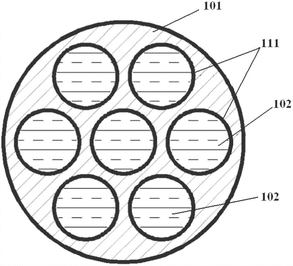
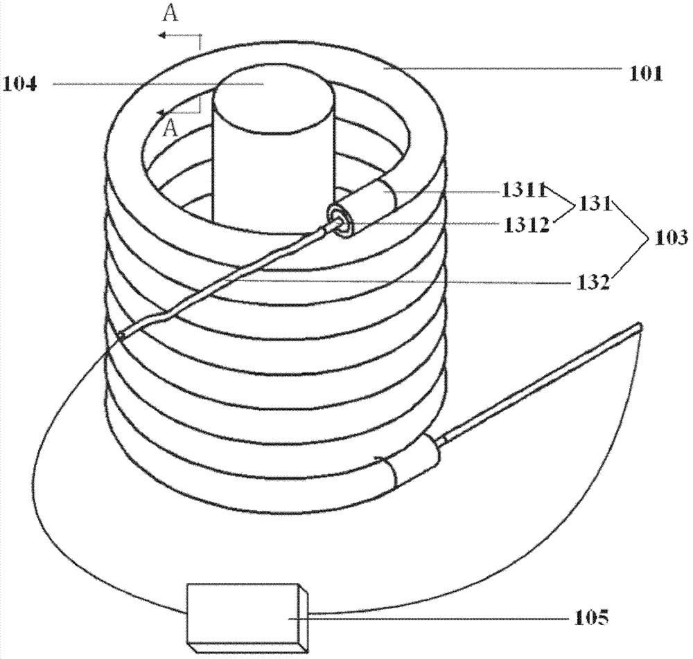
[0030] Such as figure 1 As shown, this embodiment describes a liquid conductor coil device, which includes a coil made of a conductor and a power supply 105 for supplying power to the coil. The conductor includes at least one flow channel 111 arranged in the axial direction. The insulating pipe 101 and the liquid conductor 102 filled in the flow channel 111 of the insulating pipe 101 , the power supply 105 is electrically connected to the liquid conductor 102 through the connecting body 103 .
[0031] Wherein, the power supply 105 can be a power supply in various forms such as direct current, alternating current, pulse power, etc., and parameters such as voltage and current are selected according to usage requirements.
[0032] In this embodiment, the insulating pipe 101 can be made of various plastic insulating materials or other insulating materials, such as silica gel, latex, plastic, etc., and the processing methods can be compression molding (compression molding), extrusi...
Embodiment 2
[0042] Such as Figure 4As shown, this embodiment describes a liquid conductor coil device, which includes a coil wound by a conductor and a power supply 205 for supplying power to the coil. The insulating pipe 201 and the liquid conductor filled in the flow channel of the insulating pipe 201 , the power supply 205 is electrically connected to the liquid conductor through the connecting body 203 . The device also includes an inductor core 204 inserted in the coil.
[0043] The structure of the coil and power supply 105 of this embodiment is basically the same as that of Embodiment 1, but the coil device of this embodiment also includes a liquid conductor circulation pipe 208, a drive pump 207 arranged on the liquid conductor circulation pipe 208, and The radiator 206 for cooling the liquid conductor circulation pipe 208, the two ends of the liquid conductor circulation pipe 208 are respectively connected to the two ends of the insulating pipe 201, and all the flow channels of...
Embodiment 3
[0048] In order to meet the needs of micro / nano-scale circuit systems in actual scientific research and production, the present invention can also provide a liquid conductor coil device with a corresponding size.
[0049] In this embodiment, the main structure of each component is similar to Embodiment 1 or Embodiment 2, except that the cross-sectional size of the coil (insulated pipe) made of liquid conductor is controlled within the range of micro / nano scale. Unlike the insulating pipes of conventional sizes, which are made of ordinary insulating materials and conventional processing techniques, the insulating pipes of the present invention adopt micro / nano-scale processing methods, such as photolithography, 3D printing, Chemical etching, electrolytic polishing, chemical plating, electroplating, sputtering deposition, ion plating, etc., and corresponding processing materials, such as nano-silicon dioxide, photoresist and other insulating materials. The connecting body parts ...
PUM
 Abstract
Description
Claims
Application Information