System device and method for deeply removing nitric oxide in industrial tail gas
A technology for industrial tail gas and nitrogen oxides, which is applied in the direction of chemical instruments and methods, separation methods, and dispersed particle separation, can solve problems such as high operating costs, small equipment volume, and poor mass transfer effect, and achieve small equipment volume and occupation The effect of small area and convenient operation
- Summary
- Abstract
- Description
- Claims
- Application Information
AI Technical Summary
Problems solved by technology
Method used
Image

Examples
Embodiment 1
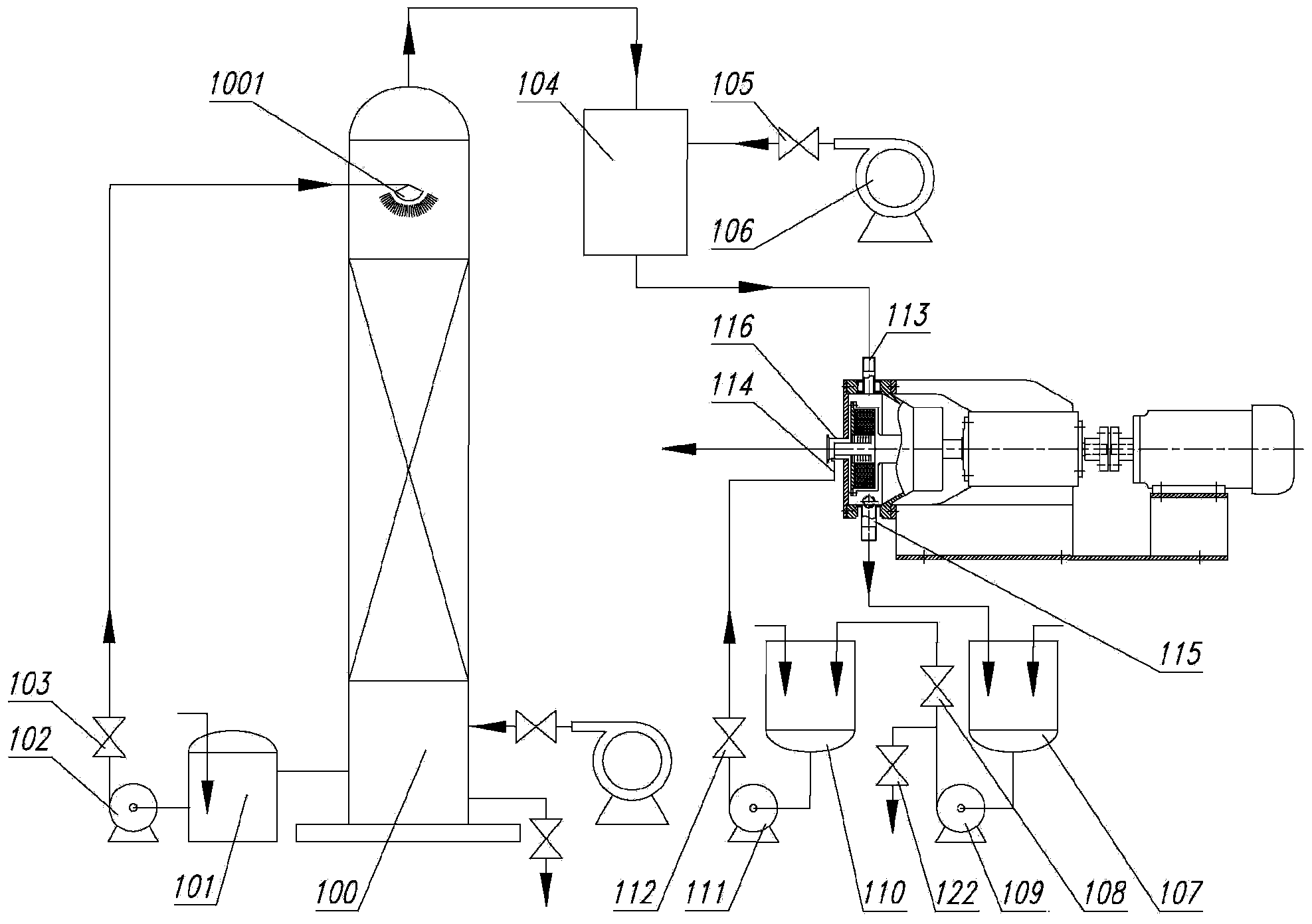
[0042] see figure 1 As shown, a system device for deep removal of nitrogen oxides in industrial tail gas includes an absorption tower 100, a first absorption liquid storage tank 101, a first delivery pump 102, a first regulating valve 103, a gas distribution tank 104, and a gas distribution tank 104. Valve 105, air distribution fan 106, supergravity rotating bed, liquid recovery tank 107, third delivery pump 109, third regulating valve 108, second absorption liquid storage tank 110, second delivery pump 111 and second regulating valve 112; The lower part of the absorption tower 100 is connected to the first absorption liquid storage tank 101 through a pipeline, and the first absorption liquid storage tank 101 is connected to the upper part of the absorption tower 100 through the first delivery pump 102 and the first regulating valve 103 in sequence. The spray head 1001 is connected and communicated; the gas outlet of the absorption tower 100 is connected and communicated with ...
Embodiment 2
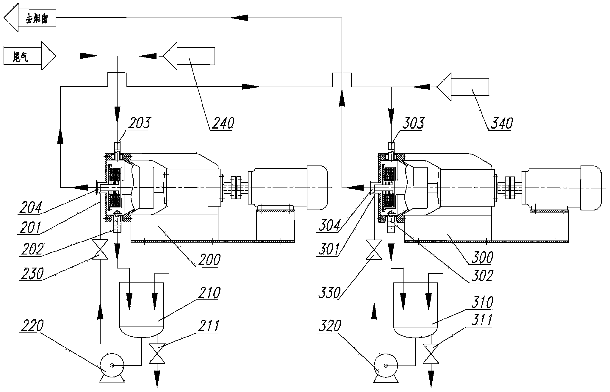
[0045] see figure 2 As shown, a system device for deep removal of nitrogen oxides in industrial tail gas includes a first-stage high-gravity rotating bed 200, a first absorption liquid storage tank 210, a first delivery pump 220, a first liquid inlet regulating valve 230, The first gas distribution device 240, the second stage high-gravity rotating bed 300, the second absorption liquid storage tank 310, the second delivery pump 320, the second liquid inlet regulating valve 330 and the second gas distribution device 340; the first stage The liquid outlet 202 of the high-gravity rotating bed 200 is connected to the first absorption liquid storage tank 210 through a pipeline, and the first absorption liquid storage tank 210 is connected to the first stage through the first delivery pump 220 and the first liquid inlet regulating valve 230 in sequence. The liquid inlet 201 of the high-gravity rotating bed 200 is connected and connected, and the first gas distribution device 240 is...
Embodiment 3
[0049] Utilize the system device of above-mentioned embodiment 1 to carry out the method for deep removal of nitrogen oxides in industrial tail gas, comprise the steps:
[0050] 1) Input the industrial tail gas containing nitrogen oxides into the bottom of the absorption tower 100;
[0051] 2) The spray head 1001 at the top of the absorption tower 100 sprays out the absorption liquid to absorb the nitrogen oxides in the tail gas, and the gas absorbed by the absorption liquid is discharged from the top of the absorption tower into the gas distribution tank 104, and the oxidizing gas in the gas distribution tank 104 After the gas undergoes an oxidation reaction, it enters the supergravity rotating bed from the gas inlet 113 for deep removal of nitrogen oxides; the absorption liquid in the absorption tower after spraying enters the first absorption liquid storage tank 101, and then passes through the first conveying The pump 102 and the first regulating valve 103 are sent to the ...
PUM
 Abstract
Description
Claims
Application Information
 - R&D
- Intellectual Property
- Life Sciences
- Materials
- Tech Scout
- Unparalleled Data Quality
- Higher Quality Content
- 60% Fewer Hallucinations
Browse by: Latest US Patents, China's latest patents, Technical Efficacy Thesaurus, Application Domain, Technology Topic, Popular Technical Reports.
© 2025 PatSnap. All rights reserved.Legal|Privacy policy|Modern Slavery Act Transparency Statement|Sitemap|About US| Contact US: help@patsnap.com