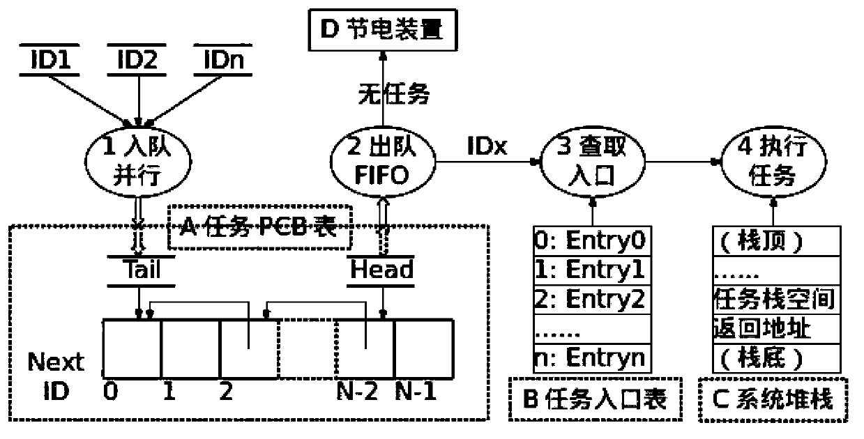
[0006] (1) Stack space problem: Deprivational scheduling may interrupt the execution process of concurrent entities at any time, so it is necessary to protect and restore the
operating environment of concurrent entities (minimum needs to include instruction registers, etc.), which requires RAM stack space
But in the case of a large number of concurrent entities (such as single-
chip microcomputers connected to thousands of networks), the problem will become quite prominent; in special occasions where RAM is scarce (such as WSN applications), scheduling will become infeasible
[0007] (2) Execution efficiency problem: due to the need to protect and restore the running environment of concurrent entities, the execution of this part of the code must be increased
In the case of very lightweight scheduling (such as TinyOS), relative to the overall
execution time of scheduling, the increased
execution time is very considerable, which seriously affects the execution efficiency of lightweight scheduling
[0008] (3) Competitive sharing problem: Deprivational scheduling may interrupt the execution process of concurrent entities at any time. Therefore, all data and resources shared between concurrent entities become objects of competition and become critical resources.
[0009] (4) Competitive reuse problem: The above-mentioned
data sharing design optimized for efficiency improvement will bring code
reusability problems
This
algorithm can avoid the potential problem of an ID entering the
queue multiple times: if the same ID can occupy multiple
byte positions, in some cases, the
byte array may be full, causing other tasks to fail to enter the queue and the
system to freeze
[0018] (2) Task information cannot be managed in a unified manner: Since the
signal light
system cannot carry parameters, the
information exchange method between the external environment and each task is completely dependent on the external environment and each task negotiated by themselves, and there is no unified and standardized means of expression
This is a great limitation to the debugging, testing, control, etc. of the
software system.
[0019] (3) The
active message cannot be fully expressed: because the
signal light system cannot carry parameters, the
information exchange method needs to be negotiated separately between the environment and the task, and it is not a unified specification
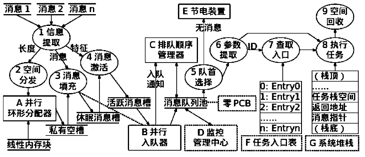
[0021] (1) Real-time performance problem: Compared with the single-
byte task ID, the message is generally longer, and it takes a long time to enter and exit the queue, which will lead to a much longer
execution time of the
critical sectionIn this way, the response speed of system interrupts will be slowed down, which will affect the real-time performance of the system and reduce the
overall efficiency of the system.
[0022] (2) Hardware implementation problem: On each processor and each
software system, the technical means to realize the protection of the
critical section of parallel enqueues are varied, and it is not easy to derive a simple, efficient and unified parallel enqueue model
[0024] (1) The entry address has a single meaning: it cannot contain other meaningful information (such as static priority)
[0025] (2) The entry address is only meaningful in a single
machine: after crossing the computer, the address has no meaning
[0029] (1) Execution efficiency problem: due to the need to perform various operations on the task PCB table (such as changing the task from the waiting state to the ready state), the execution of this part of the scheduling code must be increased
In the case of very lightweight scheduling (such as TinyOS), relative to the overall execution time of scheduling, the increased execution time is additional and considerable, which affects the execution efficiency of lightweight scheduling
[0030] (2) Hardware implementation issues: on each processor and each software system, various measures such as the content of the task PCB table, the implementation technology, and optimization methods are ever-changing, and it is not easy to derive a simple, efficient, and unified concurrent
technology implementation model
Therefore, it is not easy to use hardware to implement key operations and assist in the realization of
concurrency, and cannot improve execution efficiency or bring other advantages
[0031] (3) Space occupation problem: due to the task PCB table stored in RAM, even if the RAM usage is very small (such as TinyOS 2. In the case of scarcity (such as WSN system), if there are thousands of tasks (cases described later), the system will not be able to implement the concurrent scheduling process, which will become a fatal technical flaw and limit the scope of application of this technology
The two are inconsistent, and there are two models, which complicate the model of the basic module of the system
[0035] (3) The address scheme is difficult to adapt dynamically: during the code running period, unless it is specially maintained, the function address can no longer be tracked
[0036] (4) The function address is only meaningful in a single
machine: after crossing the computer, the address has no meaning
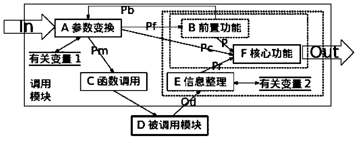
[0051] like figure 2 As shown, in the pull mode, the most fatal shortcoming is: the function call of the indivisible and must-exist C module (otherwise it is not a pull mode)
Badly designed code in the past, or code that has been barely maintained many times, will be very confusing and poor in
reusabilityIt often prompts designers to start from scratch and redevelop, unable to use existing modules and code


