Method for controlling operation of non-radial displacement sensor of bearingless permanent magnetic synchronous motor

A technology of permanent magnet synchronous motor and radial displacement, which is applied in the high-performance control of bearingless permanent magnet synchronous motor and the field of operation control of bearingless permanent magnet synchronous motor without radial displacement sensor, which can solve high-frequency signal extraction and signal filtering processing Problems such as complex process, difficult to accurately model, complex bearingless motor, etc., achieve the effect of improving system approximation accuracy, easy engineering implementation, and good generalization ability

Inactive Publication Date: 2014-01-08
JIANGSU UNIV
View PDF3 Cites 19 Cited by
  • Summary
  • Abstract
  • Description
  • Claims
  • Application Information

AI Technical Summary

Problems solved by technology

[0005] The current non-radial displacement sensor technology of bearingless permanent magnet synchronous motor mainly adopts the high-frequency excitation signal injection method, which uses the motor torque to control the mutual inductance of the winding and the suspension winding, or the relationship between the self-inductance and displacement of the suspension winding, and detects the relationship between the two ends of the suspension winding. Differential voltage is used to estimate radial displacement. This method has defects such as high-frequency signal extraction and complicated signal filtering process.
Due to the continuous injection of high-frequency voltage signals

Method used


Image

  • Method for controlling operation of non-radial displacement sensor of bearingless permanent magnetic synchronous motor
  • Method for controlling operation of non-radial displacement sensor of bearingless permanent magnetic synchronous motor
  • Method for controlling operation of non-radial displacement sensor of bearingless permanent magnetic synchronous motor

Examples


Embodiment Construction

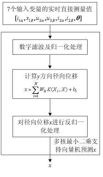
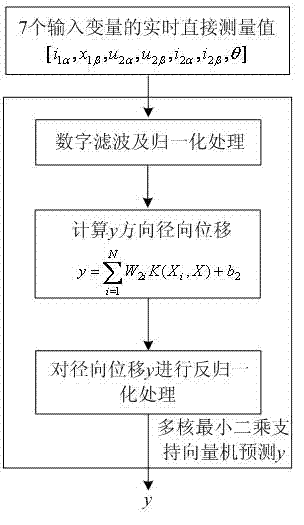
[0022] The embodiment of the present invention is: under the two-phase static coordinate system, the magnetic linkage of the suspension winding of the bearingless permanent magnet synchronous motor , Mathematical model and rotor radial displacement x , y vs. torque winding current i 1α 、i 1β , suspension winding voltage u 2α , u 2β , suspension winding current i 2α , i 2β and rotor angle θ The nonlinear mathematical model among them; design a multi-core least squares support vector machine, and construct a new equivalent kernel by linear combination of three kernel functions: polynomial kernel, exponential kernel and radial basis kernel; collect input data[ i 1α , i 1β , u 2α , u 2β , i 2α , i 2β , θ ] with output data x , y Perform preprocessing and normalization to form training samples, train the multi-core least squares support vector machine, adjust and determine the weight coefficients and thresholds of the support vector machine; construct ...


PUM


Abstract

The invention discloses a method for controlling the operation of a non-radial displacement sensor of a bearingless permanent magnetic synchronous motor. According to the method, firstly, a nonlinear mathematical model between radial displacement of a rotor and currents of a torque winding, voltage of a suspension winding, currents of the suspension winding and an angle of the rotor; then a multi-core least squares support vector machine is built by the adoption of linear combination of a polynomial kernel function, an index kernel function and a radial base kernel function; preprocessing and normalization are carried out on collected input data and collected output data, the multi-core least squares support vector machine is trained and adjusted, and a weight coefficient and a threshold value of the support vector machine are determined; a radial displacement prediction module of the multi-core least squares support vector machine is connected to the bearingless permanent magnetic synchronous motor in series; a displacement controller is designed, and the non-radial displacement sensor of the bearingless permanent magnetic synchronous motor can be controlled. A mechanical displacement sensor and an interface circuit of the mechanical displacement sensor of a prior system are removed, cost of the system is lowered, high-speed and ultra high-speed operation performance of the system is improved, and high adaptability, robustness and fault tolerance are achieved.

Description

technical field [0001] The invention relates to an operation control method for a bearingless permanent magnet synchronous motor without a radial displacement sensor based on a multi-core least squares support vector machine, which is suitable for high-performance control of the bearingless permanent magnet synchronous motor and belongs to the technical field of electric drive control equipment. Background technique [0002] The bearingless permanent magnet synchronous motor stacks the magnetic levitation control winding that generates radial force and the stator torque winding of the permanent magnet synchronous motor. By controlling the current of the torque winding and the levitation winding, the motor rotation and the stable levitation of the rotor are realized at the same time. Bearingless permanent magnet synchronous motors have the characteristics of no lubrication, no wear, no mechanical noise, etc., and can be used in biochemical and medical fields such as vacuum tec...

Claims


Application Information

Patent Timeline
IPC IPC(8): H02P21/14
Inventor 许波朱熀秋姬伟杨泽斌潘伟刁晓燕
Owner JIANGSU UNIV
Why Eureka
Try Eureka