Laser lap welding gap detecting system and laser lap welding gap detecting method based on molten pool image visual sensing

A technology of image vision and detection method, applied in laser welding equipment, welding equipment, metal processing equipment, etc., can solve the problem of not considering laser welding conditions, and achieve good real-time monitoring effect, fast response speed, and strong engineering practicability. Effect

Active Publication Date: 2014-01-15
SHANGHAI JIAO TONG UNIV
View PDF10 Cites 63 Cited by
  • Summary
  • Abstract
  • Description
  • Claims
  • Application Information

AI Technical Summary

Problems solved by technology

The image on the side away from the arc is intercepted through the image interception window for processing, and the weld deviation information is obtained by extracting the edge of the single side of the groove, which can effectively avoid the interference of the moving arc and improve the real-time performance of the weld deviation detection. The patent application It is aimed at the detection of the molten pool of narrow gap arc welding, but does not consider the situation of laser welding

Method used


Image

  • Laser lap welding gap detecting system and laser lap welding gap detecting method based on molten pool image visual sensing
  • Laser lap welding gap detecting system and laser lap welding gap detecting method based on molten pool image visual sensing
  • Laser lap welding gap detecting system and laser lap welding gap detecting method based on molten pool image visual sensing

Examples


Embodiment 1

[0036] Embodiment 1 Detection of the relationship between the gap amount and the molten pool parameters

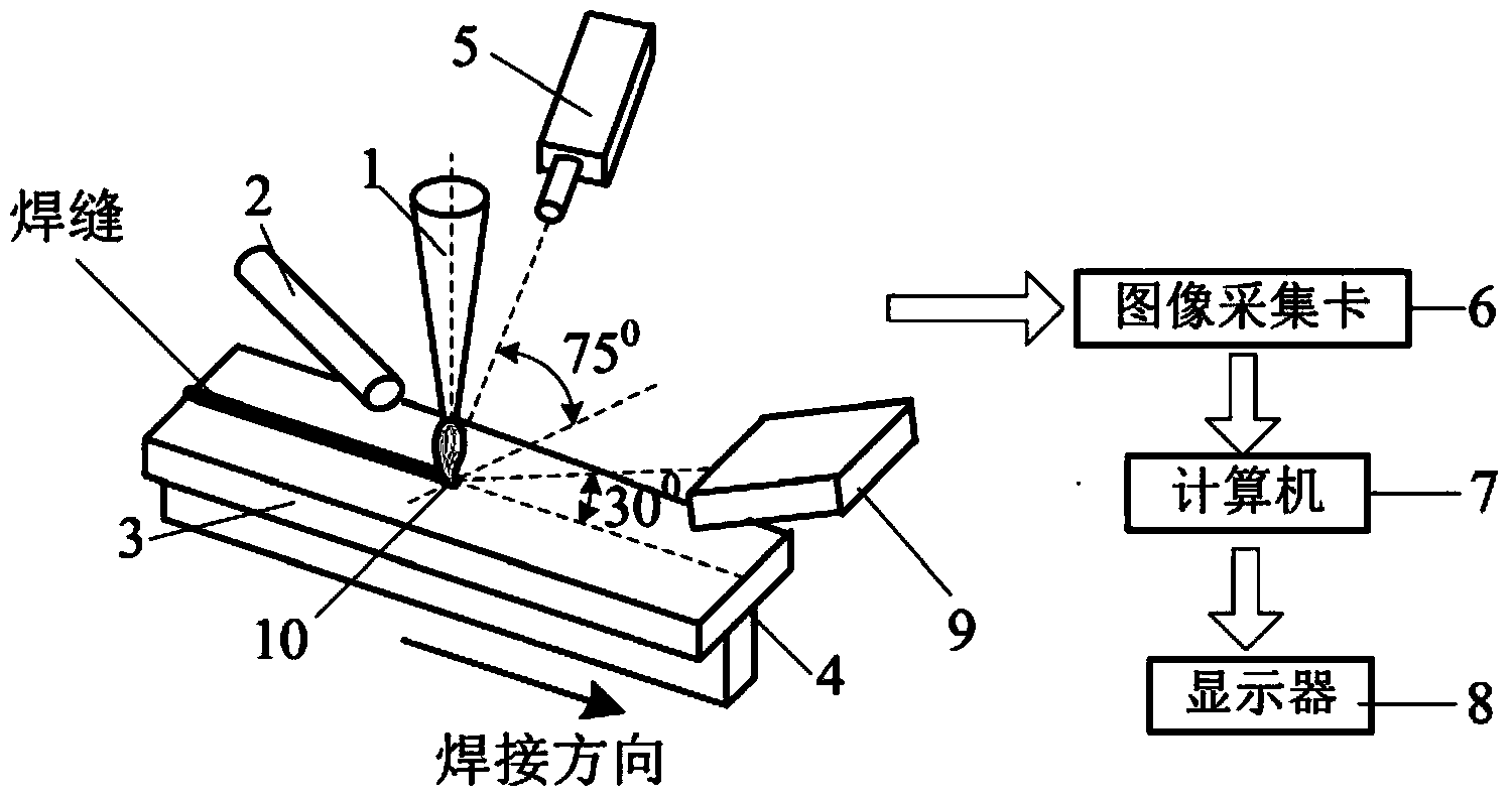
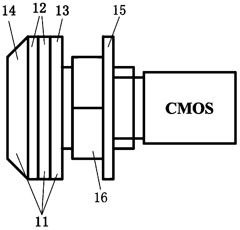
[0037] The detection method of the laser welded T-shaped lap joint gap based on molten pool image visual sensing in the present embodiment and embodiment 2 adopts the following methods: figure 1 and figure 2 The visual sensing system shown includes: a CMOS camera (5) with LinLog photosensitive technology, a filter system (11), an image acquisition card (6), a computer (7), and a display (8), wherein the computer ( 7) It is a dual-computer system composed of the image acquisition of the main computer and the image processing of the slave computer equipped with the Labview image processing platform. The main computer collects the image information of the welding area and sends it to the monitor (8) for real-time display, and the slave computer performs image processing and calculation, and Feedback to the main computer in time for image comparison and analysis to find out ...

Embodiment 2

[0054] Example 2 The actual detection of the clearance of T-shaped lap joints by laser welding

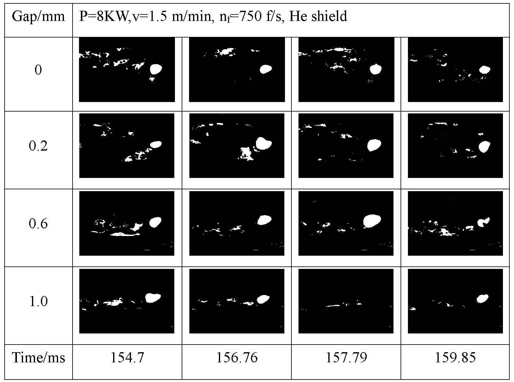
[0055]Adopt the detection system and method of embodiment 1, and utilize the relation between the laser welded T-type lap joint gap and molten pool parameter that it obtains, through to the real-time observation of molten pool image in welding process and orifice area and molten pool For the calculation of width, length and area, the following two groups of laser welded T-shaped lap joints are gap tested, and the test results are as follows: Figure 13 shown.

[0056] The monitoring results of the first group a are as follows: the length of the molten pool is 9.6mm, the area of ​​the molten pool is 44323Pixel, and the area of ​​the orifice is 2665. Through the comprehensive analysis of the above data and the dynamic characteristics of the molten pool and the orifice, it can be known that the gap in the welding process is about 0.2mm. From Figure 13 From the cross-section of the...


PUM

PropertyMeasurementUnit
wavelengthaaaaaaaaaa
lengthaaaaaaaaaa
lengthaaaaaaaaaa

Abstract

The invention discloses a laser lap welding gap detecting system and a laser lap welding gap detecting method based on molten pool image visual sensing. The detecting system is a visual sensing system and comprises a CMOS camera, a light filtering system, a secondary light source, an image capture card, a computer, a display and the like, wherein the CMOS camera has a LinLog photosensory technology. According to the detecting method, the secondary light source and emitted light of molten pools are used as light sources; plasma is filtered out by utilizing the light filtering system, and light intensity is adjusted; the computer is used for collecting and displaying molten pool images in real time, wherein the molten pool images are obtained by the CMOS camera; molten pool image edges and areas and orifice image edges and areas are extracted and calculated by utilizing a Labview image processing platform, and the quantitative relations between molten pool sizes and orifice areas and between the molten pool sizes and orifice gaps are obtained. The detecting system is simple in structure, clear in monitoring image, high in light signal detecting accuracy, strong in anti-jamming capacity, good in engineering practicability and capable of monitoring laser welding of T-type overlap joint gaps in real time.

Description

technical field [0001] The invention relates to the field of welding technology, in particular to a laser lap welding gap detection system and method based on molten pool image visual sensing. Background technique [0002] Laser welding has the advantages of large aspect ratio, small heat-affected zone and thermal deformation, and high production efficiency. In recent years, with the development of laser devices, the quality and power of laser beams have been greatly improved. Therefore, laser welding has been increasingly used used in industrial production. The laser welding process is accompanied by a variety of light, sound, heat, and electric radiation phenomena, and these signals contain a lot of information related to the welding process and welding quality. Among them, the dynamic change of the laser welding molten pool has a considerable relationship with the stability of the welding process and the occurrence of defects. At the same time, the dynamic changes of the...

Claims


Application Information

Patent Timeline
Patent Type & Authority Applications(China)
IPC IPC(8): B23K26/03B23K26/70
CPCB23K26/03B23K26/244B23K26/702
Inventor 李铸国孟威吴毅雄
Owner SHANGHAI JIAO TONG UNIV
Why Eureka
Try Eureka